
GEODUINO DEV: Power to the geoduino
We want to be able to deploy the Geoduino Seismic system as a data logger in remote locations which are off grid. It is therefore really important that we consider how to power the Geoduino efficiently.
In some settings, this might be off a lead acid (like a car battery) with solar power to recharge it. This is a common way to run these systems and great when solar power is abundant. We are hoping to be able to run this system off the same air-alkaline batteries we are running the Battman telemetry box off as this should be robust to deployment over a Scottish winter! These batteries have a limitation which is that they can only provide 50mA at 9V. We therefore need to be very confident about how much power our system will consume!
Our Geoduino Seismic ADC system contains several power hungry elements:
- Power conversion on the ESP32-S2 board (linear power converter transforms 50mA at 8V to 50mA at 3.3V (only 41% efficiency))
- Running the microcontroller (XXX around when clocking at 80Mhz)
- GPS for keeping real time clock accurate (acquisition 82mW (25mA @ 3.3V), tracking 66mW (20mA at 3.3V)))
- The external aerial also pulls a significant current even when the GPS is powered down (10mA at 3.3V)
- Writing to the SD card for logging data
- There is no direct documentation on adafruit for power usage, but the suggestion is that it can be high (upto 100mA at 3.3V). However, we are not writing large amounts of data and tests suggest this should not be problematic.
- TODO – measure this
- The data sheet suggests that the ADS1284IRHFT ADC we are using for the geophones uses 12mW in low power mode and 18mW in high power mode. At 3.3V this corresponds to 3.63mA and 5.45mA each. For all three between 11-17mA in total.
- The geoduino also contains a clock and reference voltage.
- Reading from the SD card for telemetry ()
In anticipation of the power consumption of these elements we designed so features into the Geoduino Seismic ADC board aiming to reduce the power consumption:
- Firstly, he power conversion on the ESP32-S2 is poor, we are losing more than 50% of our power at this stage
- A switching power conversion chip from TI was included on the Geoduino so that we could remove the inefficient linear converter on the ESP32-S2 development board
- According to the figure from the chips documentation, this should increase the efficiency to around 92-93%, making over twice the power available from the default linear converter
- Using the air alkaline batteries we should be able to get
 mA at 3.3V
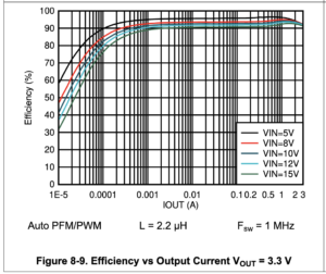
Figure 1 Efficiency of the switching power converter on the Geoduino (from the Chip makers documentation)
- Secondly, we only need to run the GPS intermittently in order to update the clock. Whilst one can put the GPS chip into standby by sending a command to the chip over the serial line, this still results in some power consumption and it is not possible to power down the external aerial which uses 10mA at 3.3V. The Geoduino contains an electronic switch specifically designed for powering down the GPS so that we can schedule updates to the ESP32-S2 clock; this requires some soldering, see figure below, and we have removed a ferrite on the power input to the GPS (TODO: check that this does not do anything bad). Note that the real time clock on the logger shield is purely to eliminate the need to a full reboot of the GPS chip when it powers up and can not provide timestamp information directly.
What we will look at here are four options for getting power into the system (Figure 2). We will talk with reference to the Adafruit ESP32-S2 Metro Express development board – but the principles are generic. One of the reasons we chose this chip and board is that everything runs at 3.3V which has advantageous power consumption. The basic workflow for all the options below is about how we convert the input voltage to 3.3V efficiently.
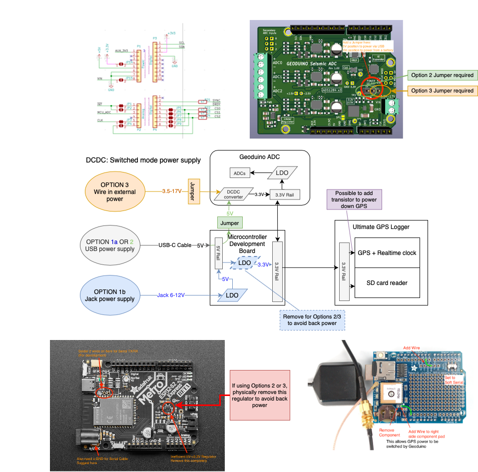
Figure 2: Schematic showing the various power routing options for the geoduino when used with the Adafruit EPS32-S2 Metro Express and the Ultimate GPS logger shield.
The ESP32-S2 Metro express and all the other electronics only requires a 3.3V power supply to run. Hence we are looking at various pathways for creating that voltage. Options 1a and 1b (see blue pathways on Figure 2) use the usb and power jack inputs to create a 3.3V power supply on the microcontroller board using an inefficient Linear Regulator (LDO). To use the more efficient routes to power the system, we need to first remove the LDO which converts the 5V to 3.3V on the microcontroller board to avoid back powering the system (LDO with a blue dashed outline in Figure 2). Option 2 routes the 5V usb input straight to a more efficient DCDC switched mode power supply to produce a 3.3V source on the Geoduino, once a jumper has been appropriately placed (green pathway in Figure 2). Alternatively, an external power supply can be directly wired into the Geoduino and routed through the same efficient DCDC converter (Open 3 is orange in Figure 2). More detail is given below.
Note that once the 5V-3.3V LDO has been removed from the ESP32-S2 development board, the Geoduino must be present to power the system!
Option 1a: Power through the USB and convert to 3.3V using LDO on ESP32-S2 dev board
When initially developing the code, this is probably the simplest method to power the system using a mains power adapter, we need this plugged into a USB anyway in order to program the microcontroller. In this lab based scenario, we are not concerned with power consumption as we are just running off the mains. In doing this, the 5V that enters the board through the USB is converted to 3.3V using an onboard Linear Regulator (LDO).
The LDO is not energy efficient and basically converted the voltage whilst keeping the current roughly constant – this dissipates a lot of potentially useful power and is too wasteful to be the field deployment power solution for us.
A second problem with powering over the USB in the field is that we may also want to use the usb port on the development board to transfer the data for telemetry so we probably dont want it tied up for powering the system.
SUMMARY: Great for lab and programming, but not practical for the field.
OPTION 1b: Power through the Jack and convert to 3.3V using LDO on ESP32-S2 dev board
A very similar system is to use the Jack on the development board. This can accept voltages in the range 6-12 V, converts this using an LDO to 5V and then uses this 5V power supply in the same way the 5V from the USB source was used. The only advantage of this is that the USB is still available for intermittent telemetry. It remains very power inefficient!
One can see from Figure 2 that once the 5V-3.3V LDO chip is removed, we can no longer generate the 3.3V power source.
OPTION 2: Power through the USB using the Geoduino’s switching power converter
This option allows us to get away from the inefficiencies of using the LDO on the development board.
We designed the Geoduino to include efficient power conversion using a switching power converter as we anticipated the problems with the LDO on the development board.
Placing a jumper in the Option 2 position allows us to connect the power from the USB on the development board to the switching power converter on the geoduino. This produces a 3.3V power source in an energy efficient manner which then powers the development board and logger shield in the normal manner.
As the signal output from a switching power converter can be noisy which matters for analogue electronics – we clean it using a specifically chosen LDO that produces the +/- 2.5V reference that is required by the ADC chips.
We don’t clean the power line that powers the digital electronics.
One should remove the LDO from the development board to avoid back powering the system – this is a hardware mod that prevents you using Option 1a/b for powering the system and therefore relies on you having a geoduino permanently attached.
This is a good way to power the system in the lab using a mains adapter plugged into the USB port for development. However, it is not ideal in the field if one is wanting to also using scheduled telemetry.
OPTION 3: Power through the battery connections on the Geoduino using the Geoduino’s switching power converter
The final option is to connect power to VIN on the Geoduino; this requires the Jumper to be in the Option 3 position. Again, this uses the Geoduino’s DCDC switching power converter to efficiently generate a 3.3V signal. VIN can be anywhere in the range 3.5-17V. This could be off a mains power adapter or from one of the air alkaline electric fence batteries. This power supply is again cleaned up using the 3.3V to +/-2.5V LDO.
Summary
The removal of the LDO from the development board changes whether we are to power the system using through the development board alone or whether we commit to using the Geoduino for the 3.3V power supply. During development of the core code in the lab, we can make do with the inefficiencies – but when we move to deployment in the field, this has to be done.
In later posts, we will look at the power consumption and optimisation choices in more detail.


Recent comments