Field Kit: Rain Gauge RG-9
Hydreon RG Rain Gauges
This link takes you to a nice video showing how the RG Rain Gauges work.
Here is a comparison of the 3 different RG Rain Gauges.
RG-9 Rain Gauge Logged using M4 Feather Express – from Open Output Collector OUT using micro python
We use the Adafruit M4 Feather Express microcontroller with an Adafruit Feather Adalogger which combines an SD card with a real time clock (RTC).
The M4 is overkill for power processor power, so we would probably be better off using the M0 Feather Express.
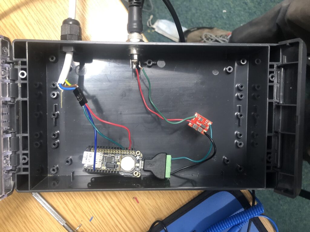
As you can see, it is in a box that is far too big, but it is what I had to hand. There is a two wire external power connector that is converted to 5V using the red buck converter and then wired into a micros connector to power the feather stack. You cannot see the M4 in the picture which is below the adalogger. The 3 core wire running through the gland goes to the rain sensor. It is powered off 3.3V (brown), connected to ground (yellow and green) and the OUT cable is in blue. I give a bit more detail below.

Checklist for deployment
- Set clock to UTC
- 6V lantern style air alkaline battery
- Feather M4 express + adalogger + buck converted in ip67 box + sensor
- microSD card reader to check or download data
- Other box to put logger and battery into
- Cable ties to keep sensor cable tidy
- Bolts / fixings for the stream gauge sensor
When the sensor is correctly powered – a green light will flash three times when it is turned on to signal it is working correctly. The green light in the middle of the sensor also comes on when it has detected rain – it is good to check this at installation to ensure it is working.
Power
There are two easy ways to power the microcontroller stack: (i) with 5V through the USB or (ii) using a LiPoly Cell. We want to run this for several months without the need to change the battery and we want to deploy over the Scottish winter when sunlight is not reliable.
I plan to use a XX aH 6V Air-Alkaline battery. The main limitation of these batteries is that the current needs to be kept under ~50mA else the battery dies very quickly. Assuming a 10mA average current, this should last for a duration = 50aH / 10mA / 24 hours = 204 days.
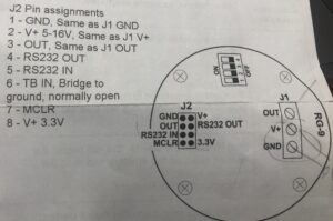
The sensor can be powered off either a 3.3V supply or a 5-16V supply on the V+ pin. The current drain of the RG-9 is low compared to the microcontroller at 110 micro Amps during normal running and 2-4 mA when it is raining. Consequently, I choose to power it off the 3.3V pin on the microcontroller.
NOTE: for future deployment I might connect the USB pin on the feather to the V+ pin in the sensor as this will mean we can screw all three wires into the sensor which will be tidier.
I choose the 6V power supply to minimise energy loss in the conversion to 5V. I use a buck-converter to do this. The input voltage range is 3~15V, it has fixed output voltage 5V, the maximum load current is 0.6A and its quiescent current is as low as 200uA.
There are handy Micro USB B Plug to 4 x Screw Terminal Connectors which, whilst not the cheapest, make it easy to power over the usb from the buck converter.
Output Signal
The RG-9 has two options for reading the output signal. We can connect to is using a serial connection OR using the OUT pin.

In this sketch we read from the OUT pin on the J1 or J2 connectors.
- OUT is pulled to ground when it is raining.
- I connect the OUT to the D6 pin on the M4 Feather express
- We can pull this pin high using micropython
- This means the pin is high when it is not raining and is pulled to ground by OUT when it is raining
Timing
I use a Real Time Clock on the Adalogger to keep track of time. Since I don’t need very precise timing, we can just use time.sleep = 300 to take a reading every 5 minutes, and we get accurate timing by writing the time from the RTC to the output file.
The other advantage of using the RTC with a watch battery to keep this accurate is that we can set the time to UTC in the lab before taking it out to the field and the time will remain accurate even though no external power is present.
It is good to always use UTC time for all data as this does not change between summer and winter.
Code
I coded this using the Mu editor – which was nice and easy.
The code is mainly based on standard sketches – the only less standard thing was that rather than reading the OUT pin status directly, we had to set a pull up resistor on the Digital 6 pin so that when OUT was pulled to ground by the sensor this became low.
The code needs to be run once to set UTC time with the appropriate flag set to True and then set this to False thereafter.
NOTE: Since writing the code below I have seen that we can use a deep sleep mode which will reduce power consumption. This works by removing the while True loop in the code below and replacing it with a deep sleep command at the end with a 5 minute wake up. Time will be kept by the real time clock which is powered by a watch battery. This also means we should remove the line that writes the header to the file. I have not implemented this yet.
import board
#import busio
import digitalio
import time

# Import Adafruit SDcard Packages
import adafruit_sdcard
import storage

# Import Adafruit RTC Packages
import adafruit_pcf8523
import busio

led = digitalio.DigitalInOut(board.LED)
led.direction = digitalio.Direction.OUTPUT

# Set pin for rain gauge sensor
rain = digitalio.DigitalInOut(board.D6)
rain.direction = digitalio.Direction.INPUT
rain.pull = digitalio.Pull.UP

# Initialise RTC
myI2C = busio.I2C(board.SCL, board.SDA)
rtc = adafruit_pcf8523.PCF8523(myI2C)
days = ("Sunday", "Monday", "Tuesday", "Wednesday", "Thursday", "Friday", "Saturday")

### use code below to set time to UTC!!!!
if False:   # change to True if you want to write the time!
    #                     year, mon, date, hour, min, sec, wday, yday, isdst
    t = time.struct_time((2022,  8,   24,   13,  04,  00,    0,   -1,    -1))
    print("Setting time to:", t)     # uncomment for debugging
    rtc.datetime = t
    print()

# Initialise SD Card
print('Initialising SC card')
cs = digitalio.DigitalInOut(board.D10)
sdcard = adafruit_sdcard.SDCard(board.SPI(), cs)
vfs = storage.VfsFat(sdcard)
storage.mount(vfs, "/sd")
print('-- SD Card Initialised')
n=0

with open("/sd/rainSensor.txt",'a') as f:
    f.write("DateTime,IsRaining\n")

while True:
    t = rtc.datetime
    text = "noRain"
    print("%d/%d/%d,%d:%02d:%02d,%s" %(t.tm_mday, t.tm_mon, t.tm_year, t.tm_hour, t.tm_min, t.tm_sec, text))

    with open("/sd/rainSensor.txt",'a') as f:
        n=n+1
        led.value = True

        t = rtc.datetime

        isNotRaining = rain.value
        print(n, isNotRaining)

        if(isNotRaining):
            rainValue="False"
            print("writing -- no rain")
        else:
            rainValue="True"
            print("writing -- raining")

        f.write("%d/%d/%d,%d:%02d:%02d,%s\n" %(t.tm_mday, t.tm_mon, t.tm_year, t.tm_hour, t.tm_min, t.tm_sec, rainValue))
        led.value = False

    time.sleep(300)


Comments are closed
Comments to this thread have been closed by the post author or by an administrator.