AntBot: Calibrating the Chassis
Once the chassis has been wired up the wheels may need to be calibrated.
Each wheel is equipped with a ‘wheel encoder’ that measures the wheel’s rotations. The next section will provide some background as to what a wheel encoder is and how they work. If you are already familiar with wheel encoders then simply note that out of the box, the encoders should provide 333 ticks per rotation and skip to the ‘Calibration’ section.
Wheel Encoders Overview
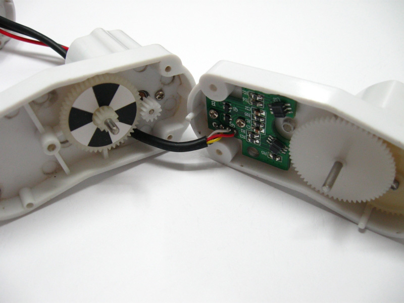
The wheels on the Rover 5 chassis are equipped with a device that allows them to self-monitor their progress called a ’wheel encoder’. Rover 5s use a type of wheel encoder called an ’optical encoder’ in which, in addition to the wheel the motor drives a disc (black/white disc on the left hand side of the image below) that is monitored by two infrared sensors embedded on the chip opposite it.
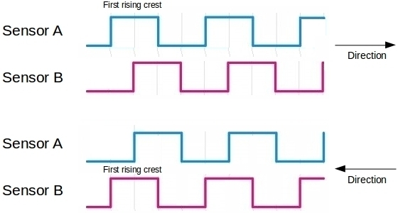
Both sensors emit a sequence of electronic pulses, responding to what they detect at any given moment, crests denote white whereas troughs denote black. Individually either wave will give speed when the frequency of it’s crests are measured. If the order of the crests in the two is compared this will give direction (blue-red is forwards, red-blue is backwards).
The term ’tick’ is used in this section to denote a crest in either individual wave. In real terms a tick means that the disc has rotated enough that the sensor from which speed is derived is reading a new segment. As the angle of each segment is the same we can convert each ’tick’ into a fixed forward or backward movement (i.e. 1 tick = x metres) and use this to record how far the AntBot has moved.
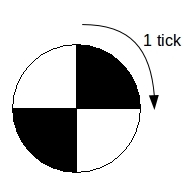
A single tick denotes that the disc has rotated enough for a single segment to elapse. According to the Rover 5 Specification, the optical disc is set up so that 333 ticks will denote a full wheel rotation.
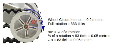
The Rover 5 specification states that 333 encoder ticks equate to a full wheel rotation and that the circumference of each wheel is 20cm. as such, we can calculate a ratio between encoder ticks and forward movement.
Calibration – Ticks
An unfortunate reality of development with Hardware is that while the spec may claim a certain accuracy – it is often the case that this will not stand in practice.
With the Rover 5, testing of AntBot found that the left wheels and right wheels have different sensitivities, as such to be able to make readings from them you need to apply a scaling factor so that they all appear to be ticking at the same rate.
The scaling should mean that all encoders are scaled up to the same range as the most sensitive encoder (as this means you will be able to monitor the wheel more closely).
The process of doing this simply involves recording how many ticks the wheels produce over a certain period (over 1 metre or over 10 seconds) and calculating the ratio accordingly. Below we can see how many ticks are produced on AntBot’s chassis with no scaling:
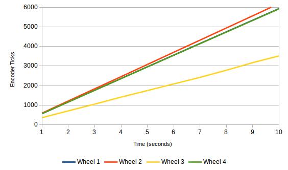
Measured over 10 seconds, wheels 1 & 2 produce the same number, 4 slightly less and 3 much less. We therefore need to scale up 3 and 4.
Wheel 3 ticks ~3500 times when it should tick ~6000 times, it’s scaling factor is therefore 1.71 (as 3500 * 1.71 = 6000). 4 is adjusted using the same process.
Calibration – PWMs
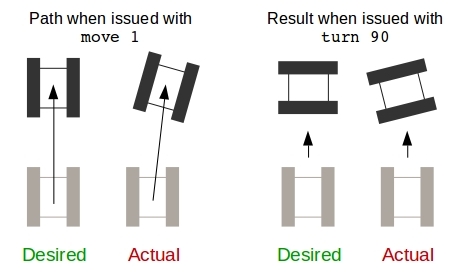
The Pulse Width Modulation is effectively the speed of rotation of the wheel. In theory, if the same PWM is given to all wheels they should start rotating at the same rate. However this often not the case – when given the same PWM the wheels may rotate at different rates and as such the robot may drift like so:
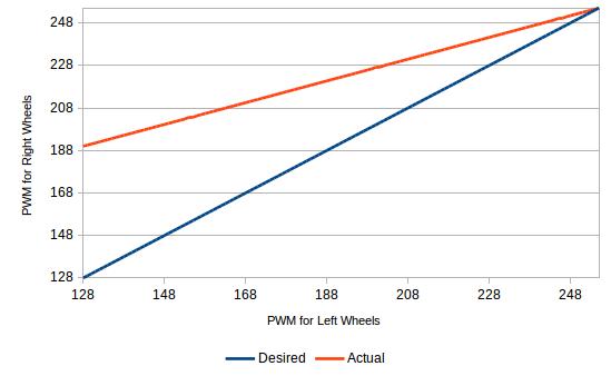
A second scaling system may need to be implemented to combat this. The scaling system would work by translating the PWM settings from one set of wheels into equivalent settings in the other that ensures the wheels spin at the same rate.
Below we can see a diagram that shows this equivalence. The blue line denotes what the PWM should be in theory (i.e. all wheels rotate a the same rate given the same PWM) and the red denotes what happens in practice (different PWMs are needed to have the same wheel spin rate).
Now it’s time to set up the development environment!