For the interactive software, I mainly use Arduino and MaxMSP (see Figure 1). Arduino is responsible for processing the information received by the sensors connected to the hardware Uno, and Max is responsible for receiving the data in the Arduino and connecting it to the Max patch for the audio and visual parts.

Figure 1: Arduino and MaxMSP Software.
Arduino
In the preliminary test, I tested the ultrasonic sensor, light sensor and temperature&humidity sensor respectively and created a separate Arduino project for each sensor.
Here are the videos and pictures of the Arduino project for each sensor.
1. Ultrasonic sensor (see Video 1 and Figure 2).
Video 1: Ultrasonic Sensor Connects to Arduino.
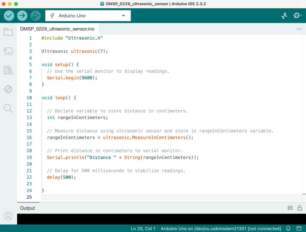
Figure 2: Ultrasonic Sensor Separate Arduino Project.
2. Light sensor (see Video 2 and Figure 3).
Video 2: Light Sensor Connects to Arduino.
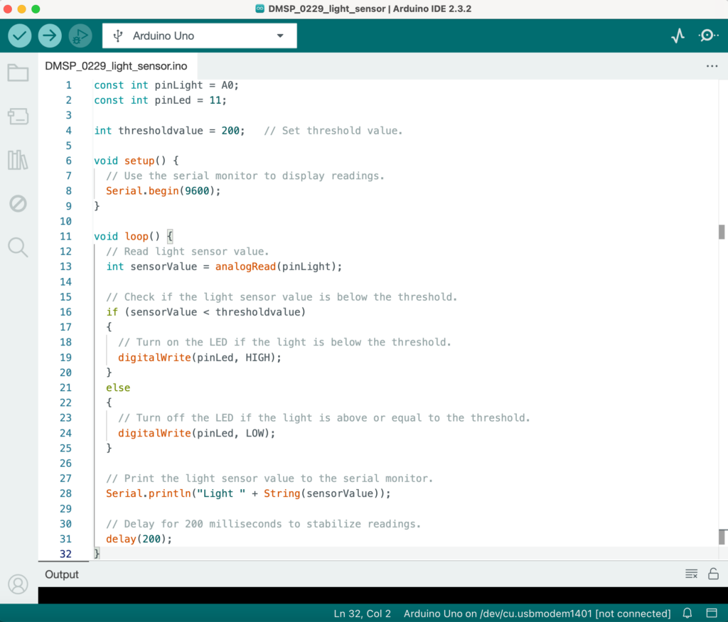
Figure 3: Light Sensor Separate Arduino Project.
3. Temperature&Humudity sensor (see Figure 4).
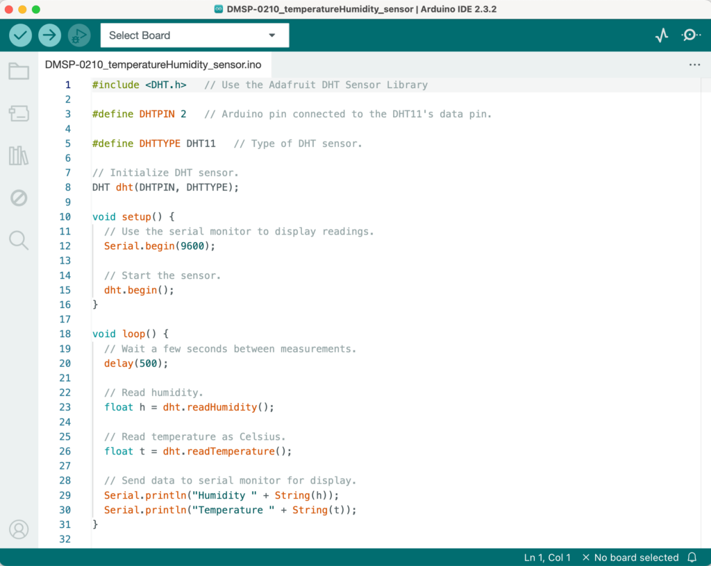
Figure 4: Temperature&Humidity Sensor Separate Arduino Project.
After several weeks of adjustments and optimization, I divided the 5 sensors in the Arduino project into two categories: Audio and Visual according to the on-site classification, thus forming two large Arduino projects. Here are the Arduino project files link: Arduino Project.
What the Visual project receives is the first ultrasonic sensor that controls pattern type changes and the first light sensor that controls pattern complexity, as well as the temperature and humidity values of the temperature&humidity sensor (see Figure 5). The Audio project receives the second ultrasonic sensor that controls the x-axis of the panner and the second light sensor that controls the y-axis (see Figure 6).
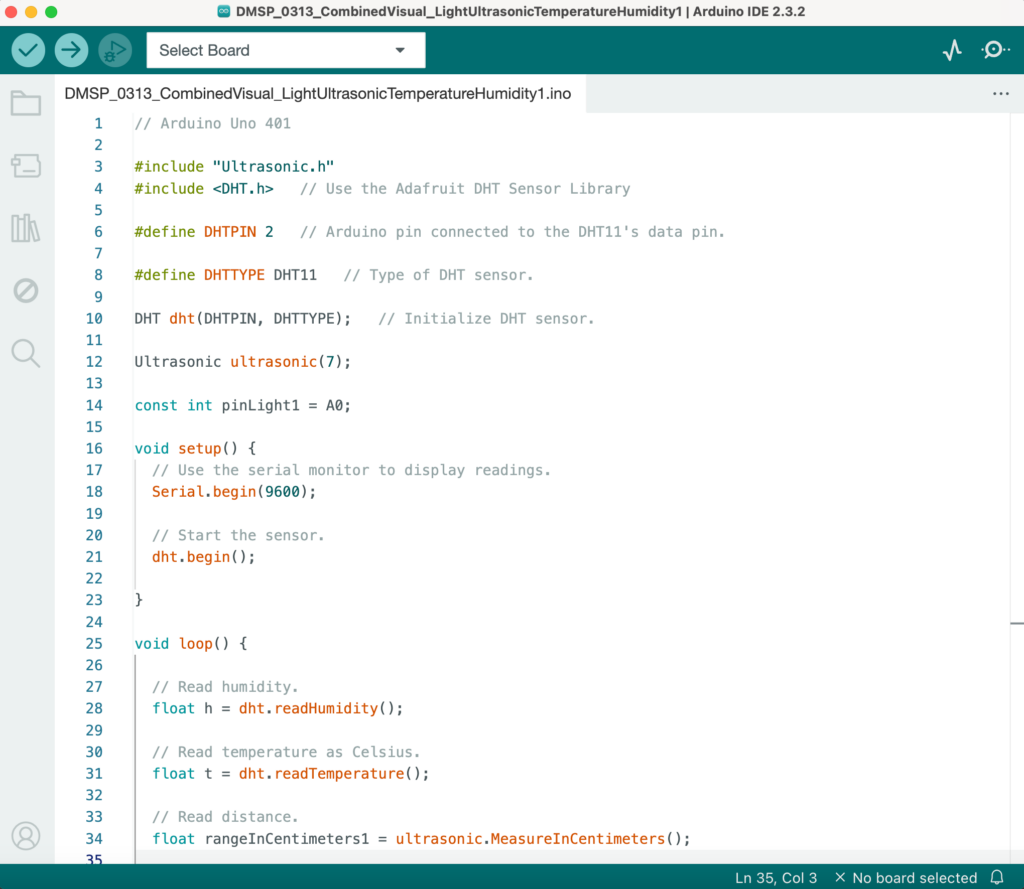
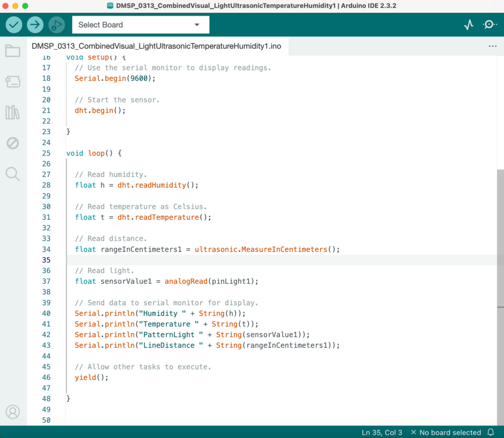
Figure 5: Arduino Project That Combines the Visual Part Sensors.
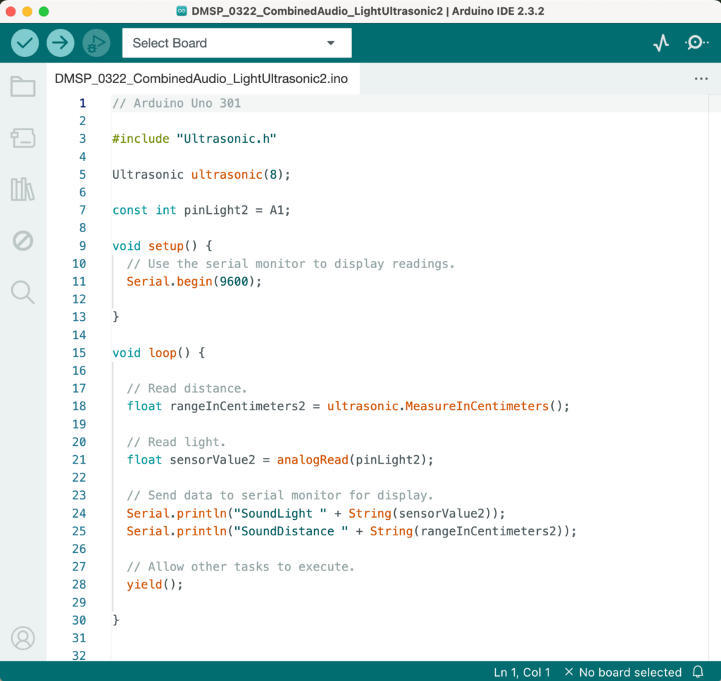
Figure 6: Arduino Project That Combines the Audio Part Sensors.
During the testing and operation of Arduino throughout the semester, I referred to a lot of relevant materials, such as the following three videos, which were of great help to my hardware and software settings.
- Using the HC-SR04 Ultrasonic Distance Sensor with Arduino.
- Light sensor Grove module.
- How to Use a DHT11 Humidity Sensor on the Arduino.
However, I still encountered many practical challenges and difficulties throughout the Arduino learning process. The main things that cost me a lot of thought are:
- How to connect multiple sensors to the same breadboard and run them successfully;
- How to modify the code in Arduino to increase the numerical sensitivity of the sensor;
- How to optimize the code in the Arduino project so that data can be sent to Max and both software can run smoothly.
After continuous research and breakthroughs and discussions with tutors, I gradually solved these difficult problems and finally got a more complete Arduino project system.
MaxMSP
The interactive part in Max is mainly the data transmission settings of sensors and MIDI controllers.
1. Sensors Part in Max.
In the sensors part, I mainly started by studying how Arduino sends data to Max. I referred to the tutorial video provided by Leo and successfully created a basic “Sending data from Arduino into Max” Max patch (see Video 3 and Figure 7).
Video 3: Sending data from Arduino into Max Tutorial.
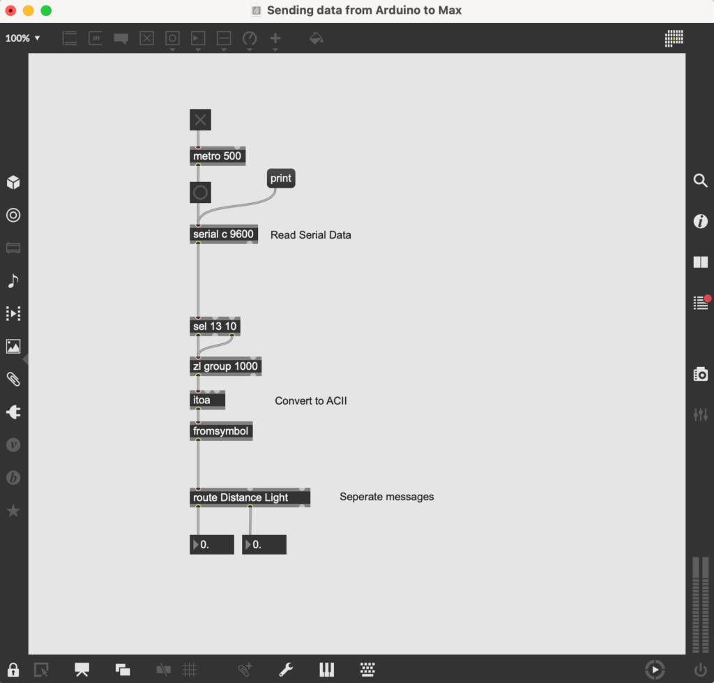
Figure 7: Sending Data From Arduino Into Max Patch.
And after that, I successfully tried running this patch using the light sensor and ultrasonic sensor (see Video 4).
Video 4: Light Sensor and Ultrasonic Sensor Sending Data to Max.
After completing these preparations, I began to formally invest in implementing the specific settings of each sensor corresponding to the specific parameters in the total Max patch. And I added objects for sending data to the visual section and audio section in the Max patch according to the determined categories. Here is the total final Max patch link: Max Patch with required audio samples.
(1) Visual Section.
The visual section mainly uses one of the ultrasonic sensors and one of the light sensors. Since the temperature and humidity sensor is connected to the same breadboard as these two sensors, it can only be placed together in the visual section (see Figure 8).
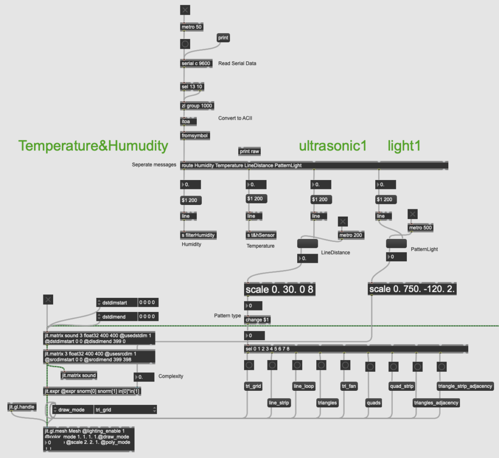
Figure 8: Sending Data from Arduino to Visual Section of Max Patch.
For the humidity and temperature values, I used send objects and receive objects to send them to the filter part and master level part respectively.
The purpose of this filter is to allow users to experience changes in sound frequency by interacting with the humidity sensor. After Leo’s guidance, I discovered that the cascade~ object can implement audio filter changes. With the filtergraph~ object, the cutoff frequency can be changed by the value received by the sensor (see Figure 9).
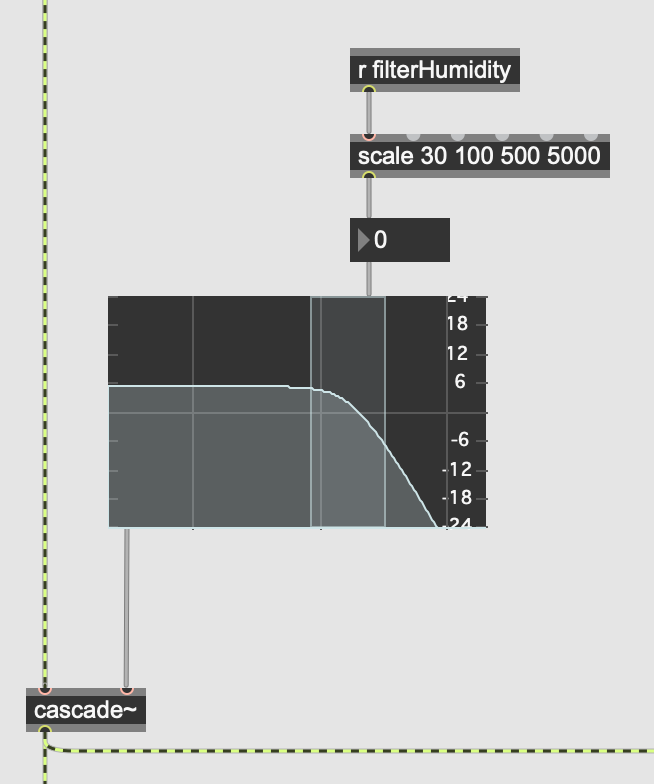
Figure 9: Filter Part in Max Patch.
The master level part is set up to avoid the phenomenon that when there are many users in the environment, they produce more sounds, resulting in some users not being able to hear the sounds emitted by the installation. So the less obvious temperature value in the temperature&humidity sensor can be used to control the master level, thus realizing the operation of adjusting the total volume invisibly according to the on-site environmental conditions. That is, the more people there are, the higher the temperature, and the greater the master sound level of the installation. Corresponding to the implementation in Max, I used the live.gain~ object set to four channels to connect it to the panner and dac~ object to achieve master level control (see Figure 10).
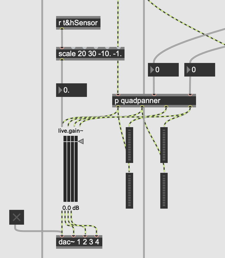
Figure 10: Master Level Part in Max Patch.
(2) Audio Section.
The audio section mainly uses the remaining ultrasonic sensor and the remaining light sensor (see Figure 11).
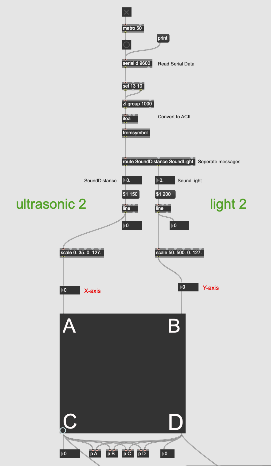
Figure 11: Sending Data from Arduino to Audio Section of Max Patch.
As can be seen from the figures above, I added a scale object after the value received by each sensor to convert it to the applicable range of each parameter. And I also added line objects in front of some parameters and set appropriate metro values for them, so that the value changes more smoothly without lag.
2. MIDI Controller Part in Max.
The role of the MIDI controller in our project is as a button for switching layers. During the rehearsal, I tested that the button on the MIDI controller we wanted to use had a corresponding value of 67 in Max, so I used the select object after notein object to select this value (see Figure 12).
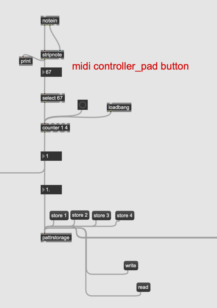
Figure 12: MIDI Controller Part in Max Patch.
However, I actually encountered difficulties during the setup process. After connecting all the objects at the beginning, I found that when I pressed the button once, the counter would count twice. Later I found out that it was because Max received the value 67 twice when I pressed the button and released the button. But what I wanted is that Max only receives the value when the button is pressed. So I sought Leo’s help, and he guided me to add a stripnote object after the notein, which can filter out the note-off information and leave only the note-on information, achieving the effect I wanted.
The final effect is that when the user presses this button, Max will receive an input of 67 values, so that the counter counts up once to achieve the purpose of switching to the next layer.
Feedback and Reflection
I received a lot of feedback on site and had some personal reflections after the final presentation. Here are the detailed descriptions: Feedback and Reflection

