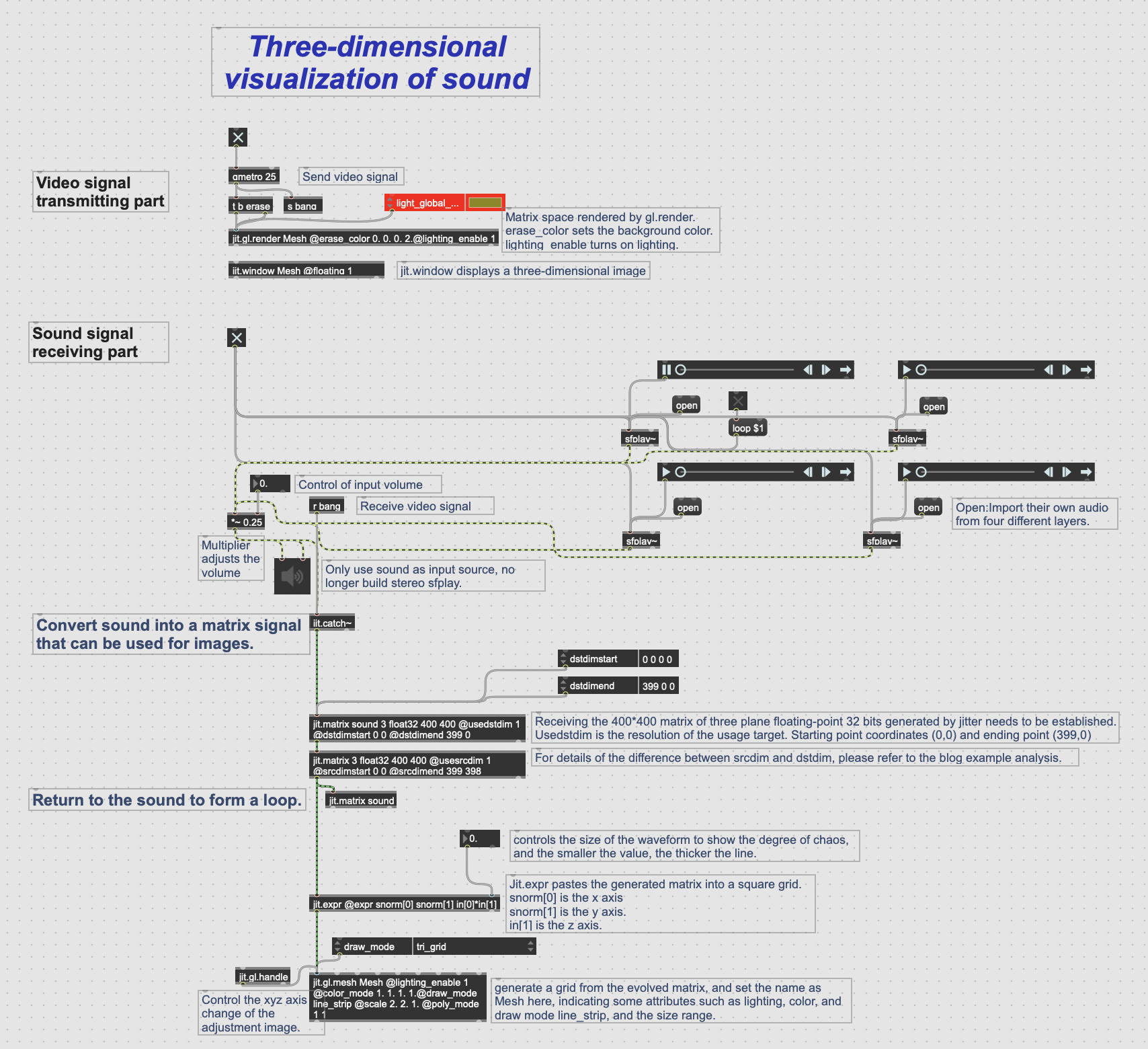
Deconstruction of visual part patch
First of all, we have to say that we are a professional group of all-sound, so we are a weak link in visual effect, and there is no fancy design. But based on my desire to try the visual aspect, I am responsible for the conception and idea of the visual part of the project.
Because we have some experience in using max for live, after discussing the original artistic concept of our group, I thought of using jitter to realize it. This can not only play our role as a sound designer, but also make the sound visual, which is very appropriate for our own professional development.
This is my primary idea—Use the imported sound to trigger the visual system to play, and then control some parameters of the sound to make the visual patterns more diverse.
In short, after the audio signal is received, it is converted into a matrix signal that can be used for images. The matrix signal is attached to the mesh, so that the change of audio can drive the change of x_y_z axis of the mesh. At the video signal sending end, the visual presentation after receiving the signal can be seen through the jit.window.
The picture is a patch annotation diagram about three-dimensional visualisation of sound.
The following is a link to the patch:https://www.dropbox.com/scl/fi/p091k40nmv145tcoim020/Three-dimensional-visualization-of-sound.maxpat?rlkey=3ni75uxbdbo1di3sht2l14xtz&dl=0
Use of srcdim and dstdim object

In the patch, you can see that I used two objects, srcdim and dstdim. The following are videos to explain the contrast of image changes caused by these two controlled parameters.
The difference between srcdim and dstdim is that the former controls the scale amplitude of the whole matrix, while the latter can update the scale amplitude of the upper or lower edge in real time. Because the audio signal is a one-dimensional matrix, after setting its X and Y axes, it will form a ground-like waveform that changes like a mountain.I use this principle to realize the change of patterns.
The following is a link to the patch about the comparison between two objects:https://www.dropbox.com/scl/fi/mbb4gf6yzz50a2a7t4d9f/dstdim-vs-srcdim.maxpat?rlkey=9t5rdkwz5nghne4sp8s7znp72&dl=0


