Overview
In this case, the Arduino plays a crucial role in the overall interactive device and sound triggering system, acting as a bridge between the distance sensor and the Max patch, enabling the interactive device to respond to the user’s actions and trigger the appropriate sound.
Its main function is to act as the primary interface between the distance sensor and the Max patch receiving the distance sensor data, processing it and sending it to the Max patch via serial communication. The Arduino code reads the sensor values from the distance sensor pins and sends them to the Max patch via serial communication. The Max patch then processes the sensor data and triggers the appropriate sound based on the received sensor value, sending a signal when the distance sensor value exceeds a specified threshold.The Arduino code is able to detect when the distance sensor value exceeds the threshold and sends a trigger signal to the Max patch via serial communication.
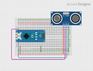
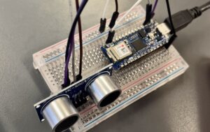
Arduino connection diagram
Arduino Operation
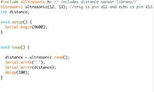
The code is used to measure the distance using the ultrasonic sensor. It uses the ultrasonic library to handle the sensor functions and provides the ability to interact with the ultrasonic sensor. The code calls the integer variable “distance” to store the measured distance. It initializes serial communication at a baud rate of 9600, which is used to send data from the Arduino to the computer via a USB connection. During the main loop run, this code sends the measured distance value to the serial monitor. Our project code introduces a 100 ms delay between distance measurements, which provides some time for the serial monitor to display the data and for the sensor to settle down between measurements. Finally this code uses the ultrasonic sensor connected to pins D12 and D13 to measure the distance and send the measured distance value to the serial monitor.
Introduction and workflow of MAX part:
Trigger sound design ideas and production process:https://blogs.ed.ac.uk/dmsp-place23/2023/03/23/interactive-trigger-sound/
Max and Arduino overall architecture testing process:
If you’re reading this in order, please proceed to the next post: ‘Point cloud data processing with CloudCompare #1 – Editing’.