Any views expressed within media held on this service are those of the contributors, should not be taken as approved or endorsed by the University, and do not necessarily reflect the views of the University in respect of any particular issue.

Integrated Sound Triggering System #1 The function and structure of MAX

Overview

The interactive sound component of the device is designed to receive data from the sensors and to map the sensed data generated by the tester in real time to the intended sound sample in Max. Therefore, in this part of the concept, the state of simulated human climbing a step is transformed into a trigger and a random event for the tester for a certain threshold range.

Max 

The Link of Max Patch(with sound libraries):

https://drive.google.com/file/d/1ylP1ThA-mZn0tlwyI7ectMkIi0DuK2zL/view?usp=sharing
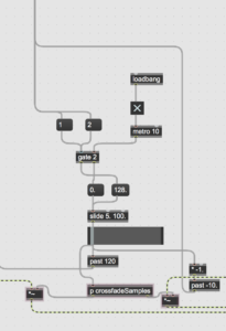
Threshold control:

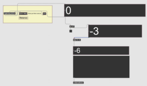
Firstly, the Max patch needs to receive distance sensor values from the Arduino. These values represent the proximity, or distance, of a person to the stairs and it changes as the person goes up or down the stairs. Max patch receives distance sensor values from the Arduino, representing the proximity or distance from the person to the stairs. It compares the received distance sensor values with the threshold values 55 and 155 to determine the different states of climbing the stairs.

When a certain threshold range is reached, the sensed data is automatically detected and a different result is triggered. For example, with 55 and 155 as the two thresholds for ResultA/B, ResultA’s Playlist is triggered when the data is less than 55, ResultB’s Playlist is triggered when the data is greater than 155, and the Playlist for intermediate state sound files is triggered when the data is between 55 and 155.

In the final Max patch, the device is triggered by two thresholds that determine the distance value in real time. the “Past” object in the Max patch simulates the state of a person climbing a staircase using the distance sensor value received via the Arduino, and the “Past” object has four states during the determination process. The thresholds 55 and 155 are used to detect when the person has climbed the stairs and returned to the middle state from the previous step, respectively. A negative threshold of opposite polarity multiplied by -1 is used to indicate the return state.

When the first threshold is triggered (going up a step), the distance sensor value crosses the threshold 55 from low to high, triggering the first threshold in the patch indicating that the person is going up the stairs. This may result in a positive value being stored in the “past” object indicating the current state of the stairs. When the second threshold is triggered (returning to the intermediate state from Step up), the distance sensor value crosses the threshold 55 from a high value to a low value, triggering a second threshold indicating that the person is returning to the intermediate state from Step up. This results in a negative value being stored in the “past” object, indicating the current state from Step back to the intermediate state. When the third threshold (going down the stairs) is triggered, the distance sensor value crosses the threshold 155 from a low value to a high value, triggering the third threshold, indicating that the person is going down the stairs, storing a positive value in the “past” object, indicating the current state of going down the stairs. When the fourth threshold is triggered (returning to the middle state from the bottom of the stairs), the distance sensor value crosses the threshold 55 from the high value to the low value, triggering the fourth threshold, indicating that the person is returning to the middle state which is the middle state at the bottom of the steps, resulting in a negative value being stored in the Past object.

It is worth noting that the negative value triggered in the above step is multiplied by -1 using the multiplication object in the Max patch. this changes the sign of the value in a mathematical sense and in this case effectively indicates the opposite direction of the return to the intermediate state from the top or bottom of the step, enabling the simulation of the change of state of the person going up and down the stairs in the Max patch.

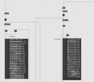
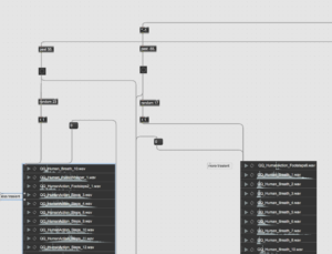
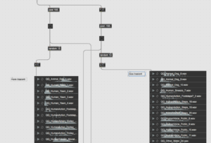
sound containers ( Random ) :

Vertically, a Playlist is created that randomly plays different fetch sound objects, i.e. containers of sound objects corresponding to the two extreme sound states of ResultA/B. Horizontally, it is necessary to create the corresponding sound containers for a range based on the actual measurement of different value intervals containing multiple transformations of the same sound file from ResultA to ResultB.

Within the framework of the above thresholds, I set up four sound playlist objects so that each time a threshold is triggered, the destination sound sample playlist can be played at random. According to the original design of the interaction-triggered sounds, the target sound playlist was broadly divided in the auditory category into realistically inclined sounds in the range of action-return states with a threshold of 55 and non-realistically inclined sounds in the range of action-return states with a threshold of 155. However, based on the results of the subsequent tests, the four sound playlists were further divided into Transient and Sustain in terms of their nature. The aim was to simulate a more realistic human speed state when walking up and down stairs.

Transients and continuations of sound:
When the observer is going up the stairs, all sounds within the random sound playlist are sustained, whereas when the person is returning to the intermediate state from a step, their simulated counterpart is the opposing state of going up the steps, so the target sample sound playlist is more transient, so the sound response triggered when returning to the intermediate state value is more rapid and more curved. The same purpose applies to the triggering of Threshold 155, but we wanted the sound triggered when descending the stairs to be more transient and Transient, and the sound response when returning from the step down to the intermediate state value to be more continuous and granular.
Transitions and connections of sound:
Since the observer is in constant motion during the action, this places certain demands on the transition between the different sound sample playlists. In the max patch we use the “gate” and “slide” objects to smooth this out. The go and return states of the threshold are sent to the left entry of gate via messages 1 and 2. The gate object receives the threshold and determines whether the input value is above or below the threshold. The output of the gate object is then sent to the slide object which controls the duration of the transition. The output of the slide object is then connected to the input of the scale object, which maps the duration value to the appropriate range for the playlist transition. The duration of the slide depends on the findings of our team’s listening experience in subsequent tests, and is the amount of time it takes to cross-fade between tracks. Loadbang and metro objects are used to trigger the transition at the appropriate time. This part of the Max patch can therefore be used to ensure that the sound playlist transitions smoothly and seamlessly according to the changing sensor input values.
Intuitive and Flexible Sound Transition Control:
In Max patches, the number 101 is used as a default or fallback value when sensor data is out of its range or not received correctly. This is a design choice used in the Max patch to handle unexpected or invalid inputs. For example, if the sensor is not sensitive enough or does not detect any input, it send an incorrect or invalid value to the Max patch. In this case, the Max patch is designed to replace the value with the default value of 101 to avoid unexpected behavior in the rest of the patch. Due to this phenomenon, our Max patch uses a “sel 101” object connected to a button object and has two outlets. The number “101” is used as an argument to the “sel” object, which means that when it receives the number 101 as input, it will output a “bang” message from the first outlet and the second exit will output whatever input is received. When the button object is pressed, it sends a “bang” message to the “sel 101” object. If the input number is 101, the first exit of the “sel 101” object will output a “bang” message, triggering some action in the Max patch. If the input number is not 101, the second exit of the “sel 101” object will output the input message unchanged. The number 101 is used as a trigger in Max patches to control a specific action or behavior. We connect its output “sel101” to a bang object that will trigger a specific function or event in the device when it receives the value 101. This is useful for handling unexpected input from distance sensors or implementing specific behaviors in your device based on this input.
Introduction and workflow of Arduino part:
Trigger sound design ideas and production process:https://blogs.ed.ac.uk/dmsp-place23/2023/03/23/interactive-trigger-sound/
Max and Arduino overall architecture testing process:
If you’re reading this in order, please proceed to the next post: ‘Integrated Sound Triggering System #2 The function and structure of Arduino’.
css.php

Report this page

To report inappropriate content on this page, please use the form below. Upon receiving your report, we will be in touch as per the Take Down Policy of the service.

Please note that personal data collected through this form is used and stored for the purposes of processing this report and communication with you.

If you are unable to report a concern about content via this form please contact the Service Owner.

Please enter an email address you wish to be contacted on. Please describe the unacceptable content in sufficient detail to allow us to locate it, and why you consider it to be unacceptable.
By submitting this report, you accept that it is accurate and that fraudulent or nuisance complaints may result in action by the University.

  Cancel