Any views expressed within media held on this service are those of the contributors, should not be taken as approved or endorsed by the University, and do not necessarily reflect the views of the University in respect of any particular issue.

Personal Blog: Final Integration with M5Sticks, OSC, and MAX

For the final phase of the project, I focused on refining and scaling our distance sensing setup. The goal was to clean up noisy sensor data, set a distance cap, connect everything to a shared network, and build a centralized system for routing and processing OSC messages in real time.

Hardware Refinement

I tested several M5StickC-Plus boards and HC-SR04 sensors, comparing consistency across units. Some sensors fluctuated too much or lost accuracy at mid-range distances. I ended up choosing the four most stable ones.

Each M5Stick was flashed with the same code, but I updated the OSC address string at the top so each sensor would send data to a different address:

String address = "/M55/distance";

Network Setup: Leo’s Router

Instead of using Joe’s mobile hotspot, I switched over to Leo’s router, which provided a more reliable connection. This was important for minimizing packet drops and keeping multiple sensors running smoothly.

const char *ssid = "LeoWiFi";
const char *password = "Presence";

The M5Sticks all send their messages to:

const IPAddress outIp(192, 168, 0, 255);
const unsigned int outPort = 8000;

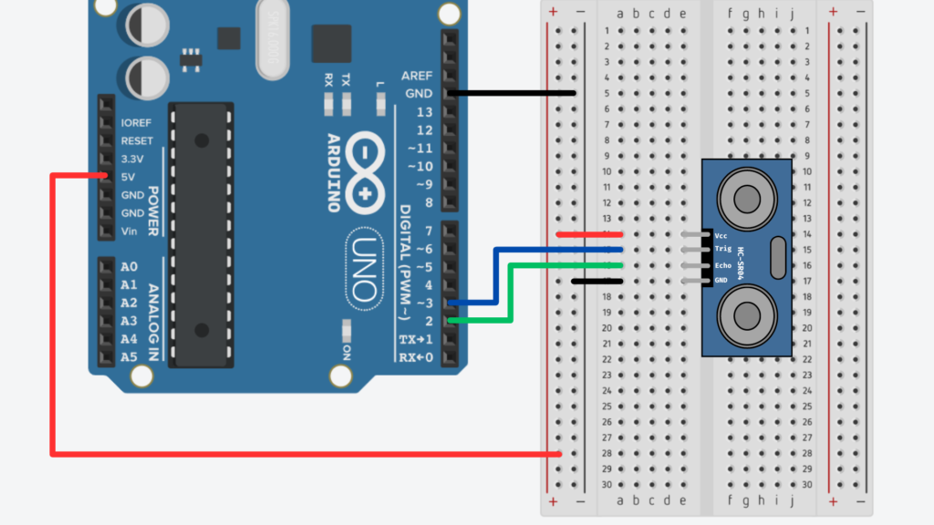
Distance Measurement and Capping

The sensor code still uses the familiar trigPin/echoPin setup. After triggering and timing the ultrasonic pulse, I added a cap to prevent noisy long-range readings:

float cm = (duration * 0.034) / 2.0;

if (cm > MAX_DISTANCE) {
  cm = MAX_DISTANCE;
}

Averaging the Distance Values

To smooth out the data, I used a rolling average over the last 10 readings. Each new value is added to a buffer, and the average is recalculated every loop.

#define NUM_SAMPLES 10

float distanceBuffer[NUM_SAMPLES] = {0};

distanceBuffer[bufferIndex] = cm;
bufferIndex = (bufferIndex + 1) % NUM_SAMPLES;

float sum = 0.0;
for (int i = 0; i < NUM_SAMPLES; i++) {
  sum += distanceBuffer[i];
}

float avgDistance = sum / NUM_SAMPLES;

Normalization for OSC Output

The averaged distance is normalized to a 0–100% scale so it’s easier to use for modulating audio or visual parameters:

float normalizedDistance = (avgDistance / MAX_DISTANCE) * 100.0;

This gives us a value like “23.4” instead of “78 cm”—much easier to use directly in Unity or TouchDesigner.

Sending the OSC Message

Once the data is ready, the M5Stick sends it as an OSC message using the CNMAT OSC library:

OSCMessage msg(address.c_str());
msg.add(normalizedDistance);

udp.beginPacket(outIp, outPort);
msg.send(udp);
udp.endPacket();
msg.empty();

Centralized Processing in Max

Rather than having each sensor talk directly to Unity or TouchDesigner, we built a central Max patch to receive and clean all OSC data.

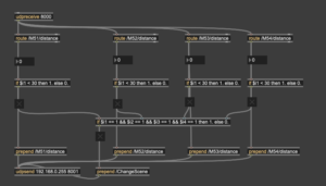
Here’s what the patch does:

  • Uses udpreceive to listen for all messages on port 8000 
  • Routes each message by OSC address (/M51/distance, /M52/distance, etc.) 
  • Compares each value to a threshold (e.g., < 30) using if objects 
  • Sends a 1 or 0 depending on whether someone is near that sensor 
  • If all sensors are triggered at once, it sends a /ChangeScene message to both Unity and TouchDesigner on port 8001 

This setup keeps the sensor logic modular and centralized—easy to debug, scale, and modify. We only need to change one patch to update the interaction logic for the entire system.
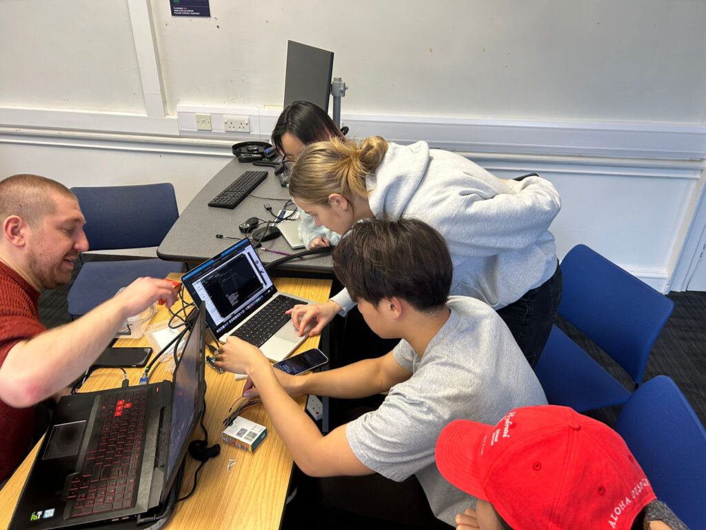
Final Testing

We tested everything together, and it worked: scene and audio changes were successfully triggered in Unity, responding to movement in front of the sensors. I also captured a video of the audio modulating based on proximity.

This system is now:

  • Scalable (thanks to Wi-Fi and OSC) 
  • Cleanly routed (through MAX) 
  • Responsive (with smoothed, normalized data) 

It’s exciting to see everything running reliably after so many small iterations.

Personal Blog: Switching to M5Sticks, OSC, and Unity

In our team meeting this week, we discussed the technical direction of our project. Up until now, I had been oversimplifying things by using a single Arduino Uno board, physically connected to my computer and sending distance data over the serial port into TouchDesigner. This worked for early tests, but it wasn’t going to scale.

We needed a setup that could support multiple sensors sending data to multiple computers: one machine running TouchDesigner for visuals, and another running Unity, integrated with Wwise, to handle spatial audio. The two systems would be kept in sync using Open Sound Control (OSC)—a protocol built for fast, real-time communication between creative applications.

After that, I had a meeting with Joe Hathaway, who pointed out that the Arduino Uno doesn’t support Wi-Fi. He recommended switching to M5StickC-Plus boards, which have built-in Wi-Fi and are well-suited for sending OSC messages wirelessly over a local network. We worked together to adapt my existing Arduino code to the M5Stick. Rather than printing values to the serial monitor, the device now connects to a personal hotspot and sends real-time OSC messages over UDP.

Code Walkthrough: M5Stick + OSC

Here’s a breakdown of the changes and additions we made in code.

1. Include Libraries and Setup Pins

We import the required libraries for the M5Stick hardware, Wi-Fi, UDP, and OSC. Then we define the trigger and echo pins for the HC-SR04 distance sensor.

#include <M5StickCPlus.h>
#include <WiFi.h>
#include <WiFiUdp.h>
#include <OSCMessage.h>

int trigPin = G0;
int echoPin = G26;

2. Wi-Fi and OSC Setup

We define the OSC address, SSID and password of the Wi-Fi network, the IP address of the receiving machine (e.g. a laptop running Unity), and the port number.

String address = "/M121/distance";

const char *ssid = "JoesPhone";
const char *password = "12345678";

const IPAddress outIp(10, 42, 218, 255);  // Receiving computer IP
const unsigned int outPort = 8000;        // OSC port

3. Setup Function

The setup() function initializes the M5Stick screen, connects to Wi-Fi, and begins listening on the network.

void setup() {
  M5.begin();
  Serial.begin(115200);
  pinMode(trigPin, OUTPUT);
  pinMode(echoPin, INPUT);

  while (!connectToWiFi()) {}
  udp.begin(outPort);

  M5.Lcd.println("Ready\n");
  M5.Lcd.println("Sending to:");
  M5.Lcd.print("IP: ");
  M5.Lcd.println(outIp);
  M5.Lcd.print("Port: ");
  M5.Lcd.println(outPort);
}

4. Loop: Distance Measurement + OSC Sending

This is the main loop that measures distance and sends it as an OSC message.

void loop() {
  // Trigger the ultrasonic pulse
  digitalWrite(trigPin, LOW);
  delayMicroseconds(2);
  digitalWrite(trigPin, HIGH);
  delayMicroseconds(10);
  digitalWrite(trigPin, LOW);

  // Measure echo time
  float duration = pulseIn(echoPin, HIGH);
  float inches = (duration * 0.0135) / 2.0;

  // Send as OSC message
  OSCMessage msg(address.c_str());
  msg.add(inches);
  udp.beginPacket(outIp, outPort);
  msg.send(udp);
  udp.endPacket();
  msg.empty();

  delay(50);  // Small pause to prevent flooding
}

5. Wi-Fi Connection Helper

This function connects the M5Stick to the defined Wi-Fi network and prints status updates to the screen.

bool connectToWiFi() {
  M5.Lcd.print("Connecting");
  WiFi.mode(WIFI_STA);
  WiFi.begin(ssid, password);

  unsigned long startAttemptTime = millis();
  while (WiFi.status() != WL_CONNECTED && millis() - startAttemptTime < 30000) {
    M5.Lcd.print(".");
    delay(400);
  }

  if (WiFi.status() != WL_CONNECTED) {
    M5.Lcd.println("\nErr: Failed to connect");
    delay(2000);
    return false;
  } else {
    M5.Lcd.println("\nConnected to:");
    M5.Lcd.println(ssid);
    M5.Lcd.println(WiFi.localIP());
    delay(2000);
    return true;
  }
}

Next Steps

Now that the M5Stick is sending OSC messages over the network, I plan to test this with my team and work through how to receive those messages in both Unity (for Wwise audio control) and TouchDesigner (for visuals). We’ll also explore setting up multiple M5Sticks on the same network and assigning each one a unique OSC address to keep things organized.

Code and diagrams adapted from Joe Hathaway, Edinburgh College of Art, 2024, used under the MIT License.

Personal Blog: Coding the Distance Sensors

This week, I focused on setting up a distance sensor. We envisioned this as the primary source of user input for our installation. The idea is to place sensors throughout the room and modulate the audio and visuals based on where the user is. All the user needs to do is move through the space, and their surroundings will noticeably shift in response.

To accomplish this, we’re using HC-SR04 ultrasonic distance sensors, which have the following pins: GND, 5V, Echo, and Trig. When the Trig pin is set to HIGH, it sends out a burst of ultrasonic sound (around 40 kHz, well above human hearing). If there’s an object in front of it, the sound reflects back, and the Echo pin reads HIGH once it detects the return pulse. From this, we can calculate the time it took for the sound to travel to the object and back—then convert that time into physical distance.

Wiring the Sensor

I followed Joe Hathaway’s guide for wiring and programming the sensors. I used female-to-male jumper wires to connect the SR04 to the Arduino Uno as follows:

Wiring Diagram
Joe Hathaway, Edinburgh College of Art, 2023

Coding the Sensors

First, I defined the trigger and echo pins in my Arduino sketch:

int trigPin = 3;
int echoPin = 2;

void setup() {
  Serial.begin(9600);
  pinMode(trigPin, OUTPUT); 
  pinMode(echoPin, INPUT);  
}

In the main loop, I began by clearing the trigger pin (setting it to LOW), then pausing for 2 microseconds to stabilize the signal:

digitalWrite(trigPin, LOW);
delayMicroseconds(2);

Then I triggered the ultrasonic burst by setting the pin HIGH for 10 microseconds:

digitalWrite(trigPin, HIGH);
delayMicroseconds(10);
digitalWrite(trigPin, LOW);

To measure how long it took for the sound to return, I used the pulseIn() function:

float duration = pulseIn(echoPin, HIGH);

This gives the round-trip travel time in microseconds. To convert that into distance:

  • Sound travels at approximately 0.034 cm per microsecond, or 0.0135 inches per microsecond.
  • Since the sound travels to the object and back, we divide by 2.

So the distance calculations look like this:

float cm = (duration * 0.034) / 2.0;

float inches = (duration * 0.0135) / 2.0;

Finally, I printed the results to the serial monitor:

Serial.print("Distance in cm = ");

Serial.print(cm);

Serial.print(", inches = ");

Serial.println(inches);

Observations and Next Steps

The sensor was pretty accurate at short distances—when I moved my hand back and forth in front of it, the values responded clearly and consistently.

At longer distances, the values became more erratic, which aligns with what Joe notes in the documentation: ultrasonic sensors can be noisy, especially over larger ranges. To improve stability, I plan to implement some smoothing—possibly by averaging several readings—and maybe add a max range limit.

Just like in my last blog (where I used a button input), I’ll bring this sensor data into TouchDesigner using a Serial DAT. I’m testing this with my group soon, and we’ll explore how to map the sensor input to real-time audio changes.

Personal Blog: Arduino Integration with Touch Designer

For our project, we wanted to create a fully immersive experience by integrating user interactions as much as possible. To achieve this, we chose Arduino to connect a variety of sensors and bring real-time interaction to the installation. Our goal is to make users feel present in the scene, with data influencing both the audio and visual elements dynamically.

We plan to use several sensors, including pulse, proximity, humidity, and light sensors. But before diving into those, we decided to start with a simple task: getting button input to work on an Arduino Uno board. This allowed us to familiarize ourselves with the hardware, wiring, and code framework before scaling up.


Day 1: Installing Arduino and Wiring the Button Circuit

We started by installing the Arduino IDE, writing basic code, and wiring a simple button circuit. Here’s a picture of that setup:

Unfortunately, we didn’t get it working on the first day. However, I went back later, referenced a wiring diagram from Arduino’s official tutorials, and got it running.


Wiring and Code

Here’s the wiring diagram I followed:


This circuit diagram is sourced from Arduino’s official documentation on wiring and programming a button (Arduino, 2024).


And here’s the simple code I wrote to print the button state from pin 2 in the Arduino IDE:


With this setup, I was able to successfully read button input. Here’s a quick demo video:


Exploring OSC Integration and Data Broadcasting

Initially, I explored the idea of using Open Sound Control (OSC) to broadcast sensor data over a network via Wi-Fi or Ethernet. The plan was for the audio and visual teams to pick up the input data from other computers. To test this, I installed Unity and worked on some integration options.

However, our team decided to simplify the setup by using Touch Designer as the central hub to handle all data, visuals, and sound. With this approach, a single computer could run the Touch Designer project and read sensor data directly from the Arduino’s serial port.


Connecting Arduino to Touch Designer

I updated my Arduino code to print button data to the serial port. In Touch Designer, I added a Serial DAT to the template and connected it to the Arduino. This allowed me to read the button state in real time within the project.

Here’s a demo of the button input working in Touch Designer:


Next Steps

My next steps involve adding multiple sensors to the circuit, printing the data in a structured format, and interpreting it in Touch Designer to control various parameters. For now, we’re simulating the data to keep the creative design process moving.

Here’s a look at the simulated button input set up to control a black-and-white filter in Touch Designer—and me smiling because it’s all working!


This progress has been a solid foundation for integrating real-time sensor data with our immersive project. More updates to come as we expand the system!

css.php

Report this page

To report inappropriate content on this page, please use the form below. Upon receiving your report, we will be in touch as per the Take Down Policy of the service.

Please note that personal data collected through this form is used and stored for the purposes of processing this report and communication with you.

If you are unable to report a concern about content via this form please contact the Service Owner.

Please enter an email address you wish to be contacted on. Please describe the unacceptable content in sufficient detail to allow us to locate it, and why you consider it to be unacceptable.
By submitting this report, you accept that it is accurate and that fraudulent or nuisance complaints may result in action by the University.

  Cancel