Any views expressed within media held on this service are those of the contributors, should not be taken as approved or endorsed by the University, and do not necessarily reflect the views of the University in respect of any particular issue.

Visual_Technical Concept

Deconstruction of visual part patch

First of all, we have to say that we are a professional group of all-sound, so we are a weak link in visual effect, and there is no fancy design. But based on my desire to try the visual aspect, I am responsible for the conception and idea of the visual part of the project.

Because we have some experience in using max for live, after discussing the original artistic concept of our group, I thought of using jitter to realize it. This can not only play our role as a sound designer, but also make the sound visual, which is very appropriate for our own professional development.

This is my primary idea—Use the imported sound to trigger the visual system to play, and then control some parameters of the sound to make the visual patterns more diverse.

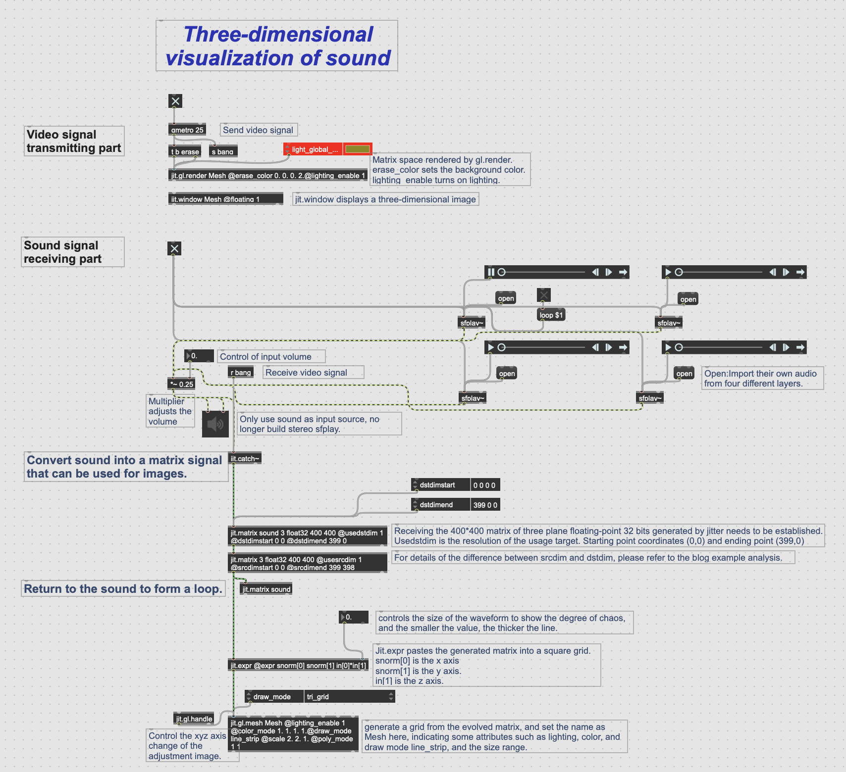
In short, after the audio signal is received, it is converted into a matrix signal that can be used for images. The matrix signal is attached to the mesh, so that the change of audio can drive the change of x_y_z axis of the mesh. At the video signal sending end, the visual presentation after receiving the signal can be seen through the jit.window.

The picture is a patch annotation diagram about three-dimensional visualisation of sound.

The following is a link to the patch:https://www.dropbox.com/scl/fi/p091k40nmv145tcoim020/Three-dimensional-visualization-of-sound.maxpat?rlkey=3ni75uxbdbo1di3sht2l14xtz&dl=0

Use of srcdim and dstdim object

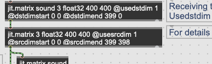
In the patch, you can see that I used two objects, srcdim and dstdim. The following are videos to explain the contrast of image changes caused by these two controlled parameters.

The difference between srcdim and dstdim is that the former controls the scale amplitude of the whole matrix, while the latter can update the scale amplitude of the upper or lower edge in real time. Because the audio signal is a one-dimensional matrix, after setting its X and Y axes, it will form a ground-like waveform that changes like a mountain.I use this principle to realize the change of patterns.

The following is a link to the patch about the comparison between two objects:https://www.dropbox.com/scl/fi/mbb4gf6yzz50a2a7t4d9f/dstdim-vs-srcdim.maxpat?rlkey=9t5rdkwz5nghne4sp8s7znp72&dl=0


Week5_Sensors_Connection_Jingqi Chen

This week I mainly explored the sensor connection part a bit more (see Figure 1). Based on the previous successful connection and operation of the sound sensor and temperature and humidity sensor, I also successfully connected and operated the light sensor and ultrasonic sensor. Variables that affect changes in each sensor will be mapped to triggering conditions for user interaction in the final installation, which is interesting for users to deepen their actual experience of “Presence”. After testing a variety of sensors, I found that these two sensors are relatively easier to implement in terms of layout and simplicity. Their interaction conditions are more suitable for our final installation. Users only need to perform some simple interactions to complete interesting operations.

The first is the light sensor (see Figure 2 and Figure 3). When the brightness received by the sensor changes, the value generated by the sensor will also change accordingly. Corresponding to the final installation, the interaction form is roughly that users cover the corresponding position of the sensor with their hands to change sound effects, music or images, etc.

Figure 2: A Photo of Light Sensor Connecting.

Figure 3: A Screenshot of the Light Sensor from Arduino.

Next is the ultrasonic sensor (see Video 1 and Figure 4). It works by identifying the distance between the sensor and the nearest object in front of it and changing the generated value accordingly. Currently, this is the sensor with the simplest form of interaction. As the user walks past the sensor, the corresponding audio or video will undergo some changes. It excels in its sense of interactivity and immediacy.

Video 1: A Video Showing Ultrasonic Sensor Connecting.

Figure 4: A Screenshot of the Ultrasonic Sensor from Arduino.

This week comes to an end on the connection between the sensors and Arduino. Next week’s tasks will focus on how to connect the Arduino to the Max and send data to the Max.

css.php

Report this page

To report inappropriate content on this page, please use the form below. Upon receiving your report, we will be in touch as per the Take Down Policy of the service.

Please note that personal data collected through this form is used and stored for the purposes of processing this report and communication with you.

If you are unable to report a concern about content via this form please contact the Service Owner.

Please enter an email address you wish to be contacted on. Please describe the unacceptable content in sufficient detail to allow us to locate it, and why you consider it to be unacceptable.
By submitting this report, you accept that it is accurate and that fraudulent or nuisance complaints may result in action by the University.

  Cancel