Any views expressed within media held on this service are those of the contributors, should not be taken as approved or endorsed by the University, and do not necessarily reflect the views of the University in respect of any particular issue.

Week8_Project_Integration_Jingqi Chen

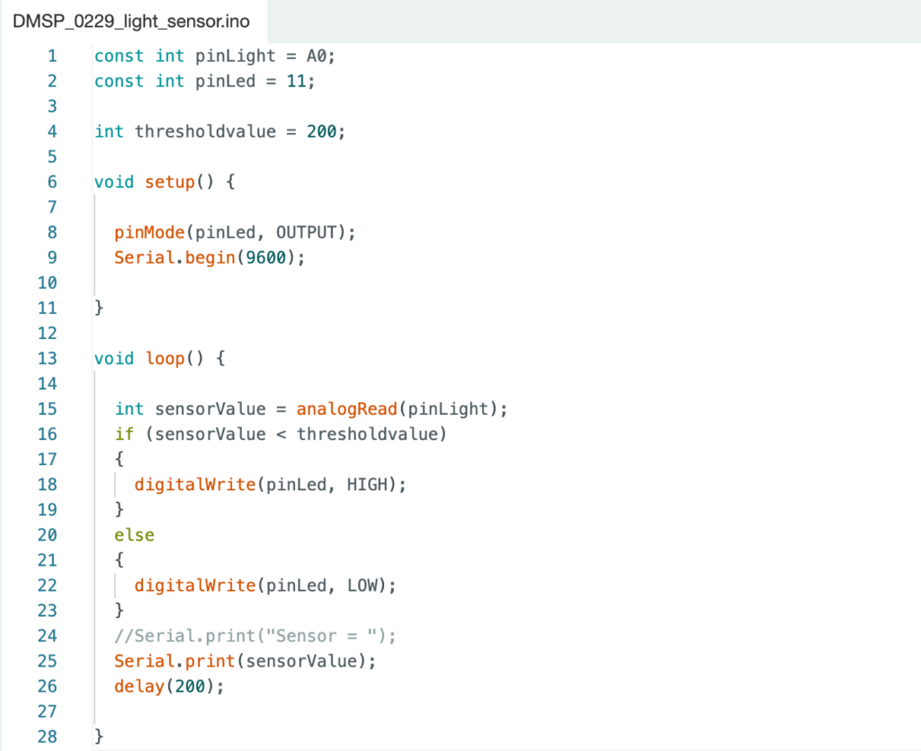
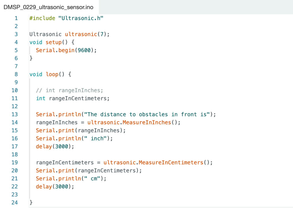
In Week 8, I mainly integrated the project files from last week, so that two sensors can be connected to the same breadboard, and the values ​​​​of the two sensors are concentrated in the same Arduino project and the same part of the Max patch (see Figure 1 and Figure 2).

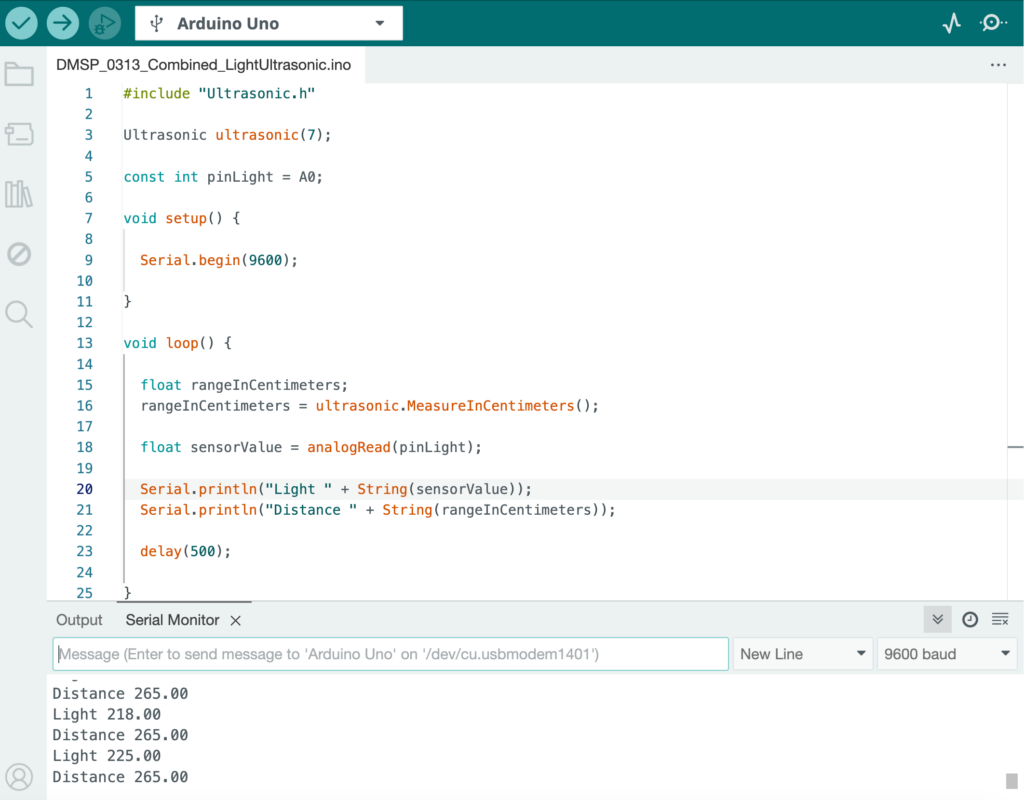
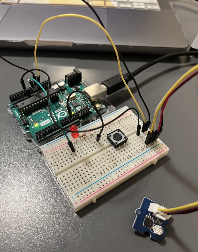
Figure 1: Arduino Project Combining Light Sensor and Ultrasonic Sensor.

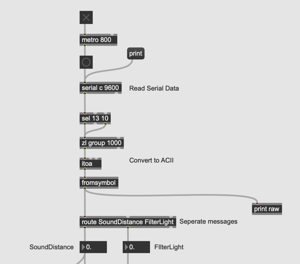
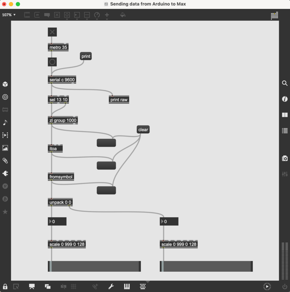
Figure 2: Max Patch that Combines Data Sent by Light Sensor and Ultrasonic Sensor.

In this way, during the testing phase and the final installation operation phase, the values ​​of different sensors can be more clearly assigned to different parameters that need to be controlled. At the same time, it can ensure whether the sensors are working properly and errors can be eliminated relatively quickly (see Video 1).

Video 1: A Video Showing the Light Sensor and Ultrasonic Sensor Connected on the Same Breadboard and Sending Data to the Max Together.

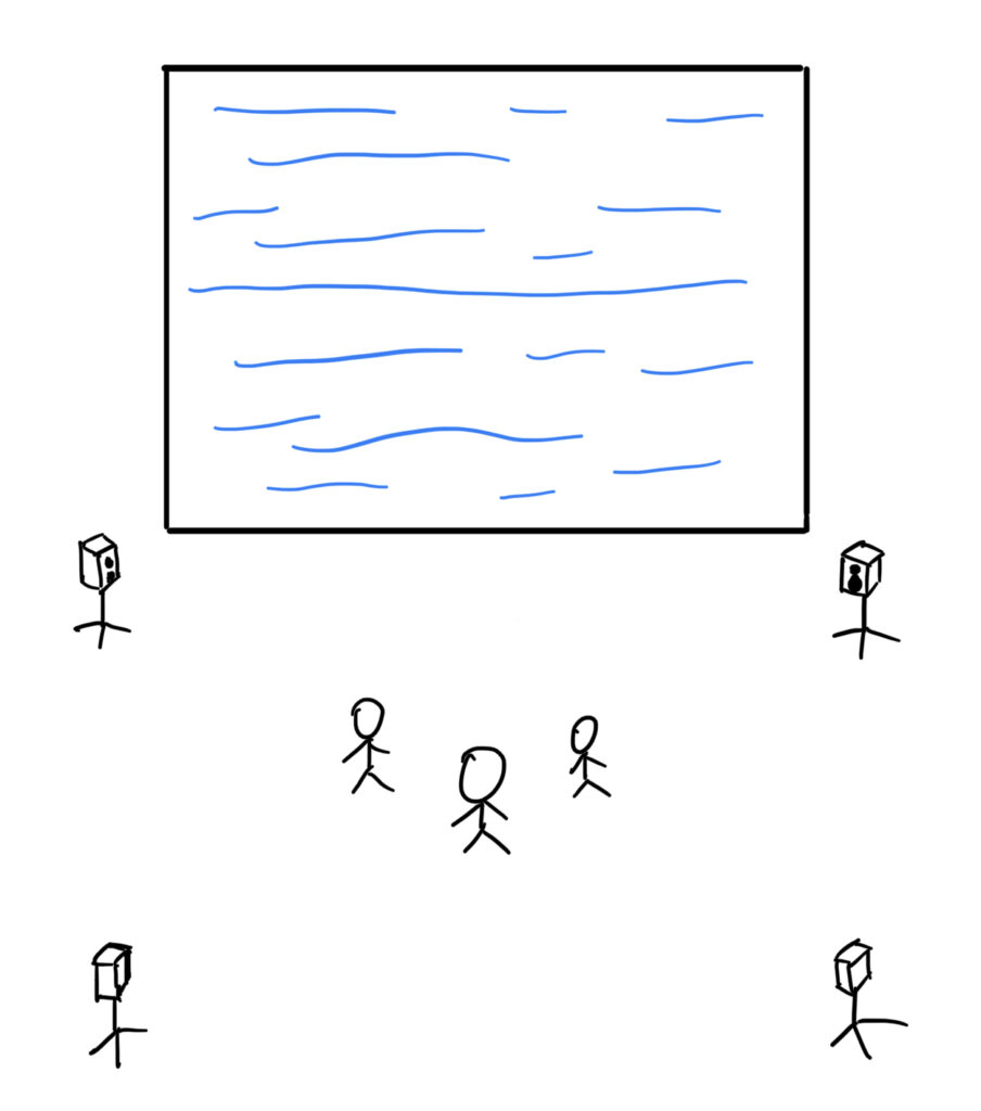
However, another problem discovered this week is that the pattern in the visual part in the Max patch cannot be displayed normally in the Mesh. Patterns that should keep beating will get stuck. This is the main tougher issue that needs to be addressed before next week.

Week7_Project_Improvement_Jingqi Chen

This week I mainly discussed with Joe and Leo the problem of equipment delay that I encountered last week and solved it. Currently, the signal received by the sensor can be sent to Max through Arduino normally. In addition to solving technical problems, this week I also focused on thinking about what sensors to use to control which parameters, and the conditions that trigger entry to the next layer.

After testing the temperature and humidity sensor, light sensor and ultrasonic sensor, it can be seen that the value of the temperature and humidity sensor changes relatively slowly, so it can be used to control some changes in the environment. For example, the more people enter the room, the higher the temperature and humidity will be, thereby changing the ambient sound level or other interesting parameters. The light sensor and ultrasonic sensor change values ​​relatively quickly and are suitable for controlling some parameters that require significant changes. Therefore, changes in sound effects, music and visual patterns are mainly controlled by these two sensors (see Video 1 and Video 2).

Video 1: A Video Showing the Value in the Max Patch Controlled by Light Sensor.

Video 2: A Video Showing the Value in the Max Patch Controlled by Ultrasonic Sensor.

In addition to this, I also briefly designed a placement diagram for the final installation. This will be improved as appropriate in subsequent rehearsals (see Figure 1).

Figure 1: A diagram showing a brief arrangement of the installation.

Week6_Arduino_Max_Connection_Jingqi Chen

The main work I am doing this week is the second subsection of the Interaction Part, which is the connection between Arduino and Max. By communicating with Leo and searching for relevant information on the Internet, I compiled a main patch for sending data from Arduino to Max (see Figure 1).

Figure 1: A Screenshot of Max Patch that Runs the Operation of Sending Data from Arduino to Max.

After the port in the serial object corresponds to the connected USB, it means that the serial object has received the data sent from Arduino, so the “print raw” object will cause the value to be printed out in the console according to the delay time interval set in Arduino, and the corresponding data groups will also be displayed in the following three message objects.

I tried to send the Arduino data of the ultrasonic sensor directly to the Max patch in the visual part made by Ruojing to change some parameters (see Video 1).

Video 1: A Video Showing the Ultrasonic Sensor Arduino Project Sending Data to the Visual Max Patch.

It ran successfully, but at the beginning I found that when the delay value was too small, that is, when the time interval between the two data generation was too short, Max could not work properly, and there was a very large lag. However, after increasing the delay value, although it can run normally, the data changes too slowly and is not suitable for the actual operation of our final installation. So the bigger problem I am currently encountering is how to balance and coordinate the actual operating rate of the equipment and the required operating rate of the installation. This is also what I will mainly need to work on over the next few weeks.

Week5_Sensors_Connection_Jingqi Chen

This week I mainly explored the sensor connection part a bit more (see Figure 1). Based on the previous successful connection and operation of the sound sensor and temperature and humidity sensor, I also successfully connected and operated the light sensor and ultrasonic sensor. Variables that affect changes in each sensor will be mapped to triggering conditions for user interaction in the final installation, which is interesting for users to deepen their actual experience of “Presence”. After testing a variety of sensors, I found that these two sensors are relatively easier to implement in terms of layout and simplicity. Their interaction conditions are more suitable for our final installation. Users only need to perform some simple interactions to complete interesting operations.

The first is the light sensor (see Figure 2 and Figure 3). When the brightness received by the sensor changes, the value generated by the sensor will also change accordingly. Corresponding to the final installation, the interaction form is roughly that users cover the corresponding position of the sensor with their hands to change sound effects, music or images, etc.

Figure 2: A Photo of Light Sensor Connecting.

Figure 3: A Screenshot of the Light Sensor from Arduino.

Next is the ultrasonic sensor (see Video 1 and Figure 4). It works by identifying the distance between the sensor and the nearest object in front of it and changing the generated value accordingly. Currently, this is the sensor with the simplest form of interaction. As the user walks past the sensor, the corresponding audio or video will undergo some changes. It excels in its sense of interactivity and immediacy.

Video 1: A Video Showing Ultrasonic Sensor Connecting.

Figure 4: A Screenshot of the Ultrasonic Sensor from Arduino.

This week comes to an end on the connection between the sensors and Arduino. Next week’s tasks will focus on how to connect the Arduino to the Max and send data to the Max.

week2_ideas_Jingqi Chen

Presence makes me think of the fact that although people physically exist in the real world, there is often a piece of their own “virtual world” in everyone’s heart, where there is a scene completely different from the real world, like the ideal country of presence that contains everyone’s consciousness. So the “presence” of the difference or the link between the real world and the virtual world is something that I want the participants to experience in an immersive way.

The following is an outline of a feasible theme that I have temporarily summarized according to our ideas we put forward in class. On top of that I added a few details, some illustrations and examples.

  • Software:Unity
  • Technology:VR <We can try to do VR with unity first, and if the implementation is not suitable in the future, we can change to lighting>
  • Theme:Feel the presence/coexistence of the real world/negative emotions(stress, anxiety, depression…)and the virtual world/positive emotions(unpredictable, unknown, intrigued…).
  • Form

  • Content

Real World:There are many doors in a narrow corridor, and when the player opens the doors, the corresponding pictures begin to show the real world (anxiety at work, irritability at school, panic at family arguments…).

Virtual World:After the player comes out of the corridor is an unknown only white environment, from time to time there may be some magical phenomena, such as a piano that no one is playing makes a beautiful piano sound.

  • Sound

Real World:realistic, immersive 

Virtual World:large reverb and delay, electronic

css.php

Report this page

To report inappropriate content on this page, please use the form below. Upon receiving your report, we will be in touch as per the Take Down Policy of the service.

Please note that personal data collected through this form is used and stored for the purposes of processing this report and communication with you.

If you are unable to report a concern about content via this form please contact the Service Owner.

Please enter an email address you wish to be contacted on. Please describe the unacceptable content in sufficient detail to allow us to locate it, and why you consider it to be unacceptable.
By submitting this report, you accept that it is accurate and that fraudulent or nuisance complaints may result in action by the University.

  Cancel