Any views expressed within media held on this service are those of the contributors, should not be taken as approved or endorsed by the University, and do not necessarily reflect the views of the University in respect of any particular issue.

Immersion vs Presence

Time for a more studious post now:

After attending a lecture about Virtual Reality, where the concepts of immersion and presence where discussed, it got me thinking. Is what we are achieving in this project immersive? How are we able to convey a sense of presence for the audience?

Let’s look at the definitions of both immersion and presence, how each are quantified and applied in this situation. The research that follows will focus on the terms in relation to technology and art exhibitions.

Immersion

Slater and Wilber (1997) define immersion as a description of a technology, and describe the extent to which the computer displays are capable of delivering an inclusive, extensive, surrounding and vivid illusion of reality to the senses of a human participant. The idea of immersive fallacy, is one that says the pleasure of a media experience lies in its ability to sensually transport the participant into an illusory, simulated reality (Salen and Zimmerman, 2003). VR is usually viewed as the most immersive form of technology. So how can an exhibition be immersive without this? And how would you quantify the experience as being immersive?

Regarding these definitions, it can be seen that immersion is a wide scale and therefore you cannot simply say whether an experience is immersive or not. However, it is possible to look at sub categories of immersion in the context of an experience. Similar to the idea of immersive fallacy, an immersive escapism experience is where a participants emotional state make them feel as if their body has separated from themselves and no longer exists. This is often the main motivation for the attendance of festivals and exhibitions (Manthiou et al., 2014; Sobitan and Vlachos, 2020; Guo et al., 2021). Another sub category, is an immersive educational experience. This is when an engaging environment is presented that is highly interactive at virtual AND physical levels (Dennison & Oliver, 2013).

Presence

The sense of presence, defined by Gruter and Myrach (2012) describes “the subjective experience of feeling present in a non-physical space”.  This is an overarching definition of the term. When technology is added into the equation, the term presence changes to “telepresence” and is shortened to “presence”. The International Society for Presence Research defines the concept of presence as a psychological state in which a person fails to fully acknowledge the role of technology in their experience, even though they are aware that they are using it. Their perception of objects, events, entities, and environments is not fully influenced by the technology involved. (Ispr.info, 2000)

It occurs during an encounter with technology, it is a multidimensional concept. They say that presence is greater when a technology user’s perceptions only partially acknowledge the actual role of the technology in the experience. Presence is the property of the individual and varies across people and time.

The concept of presence is needed for the connection between people and the virtual surroundings (Grassi, Giaggioli and Riva, 2008).  According to Sastry and Boyd (1998), the sense of presence arises from the interaction of the user with the environment. In order to feel present, you need to give people the chance to choose, to move objects in the context. It’s important for technology to be invisible to the user, so the subject can focus on the task instead of the medium: the better a medium supports the subject’s actions, the greater the sense of presence.


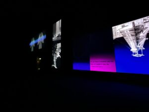
I believe that there are aspects from the main definition of immersion as well as the two subcategories that relate to how we want this exhibition to be an immersive experience. We are aiming to create a surrounding and vivid illusion of reality that, when combined with audio sensory input and the added interaction being a physical movement, will allow users to be immersed in the exhibition.

For the sense of presence in relation to this project, we are giving the user the option to control their experience through the physical interaction. The technology of the Arduino sensors is mostly invisible to the user as it is small and hidden in the shadows. The users attention is captured by the visual and sound response to their movements, therefore they are focusing more on the task and are more present during the experience.

To conclude, this project is both immersive and conveys a sense of presence for the user. Whilst perhaps not “fully immersive” in the sense that VR would be, this experience uses interactive, non-invasive technology in a space that is constructed to be surrounding the user for a multidimensional and multi-sensory exhibition.

If you’re reading this in order, please proceed to the next post: ‘Place and Non-Place’.

Molly Munro

References

Carù, A. Carbonare, P. Ostillio, M. Piancatelli, C. (2020). The impact of technology on visitor immersion in art exhibitions. In: Massi, M. Vecco, M. Lin, Y. (Ed). Digital Transformation in the Cultural and Creative Industries: Production, Cons. London: Routledge. pp.13-31.

Dennison, W. and Oliver, P. (2013) ‘Studying Nature In Situ : Immersive Education for Better Integrated Water Management’, Journal of Contemporary Water Research & Education, 150(1), pp. 26–33. Available at: https://doi.org/10.1111/j.1936-704X.2013.03139.x.

Grassi, A., Giaggioli, A. and Riva, G. (2008) ‘The influence of media content and media form in sense of presence: a preliminary study’, in. Presence 2008. Procs of the 11th Annual intl workshop on presence, pp. 258–259.

Guo, K. et al. (2021) ‘Immersive Digital Tourism: The Role of Multisensory Cues in Digital Museum Experiences’, Journal of Hospitality & Tourism Research, p. 109634802110303. Available at: https://doi.org/10.1177/10963480211030319.

Ispr.info. (2000). Presence defined. [online] Available at: https://ispr.info/about-presence-2/about-presence/.

Manthiou, A. et al. (2014) ‘The experience economy approach to festival marketing: vivid memory and attendee loyalty’, Journal of Services Marketing, 28(1), pp. 22–35. Available at: https://doi.org/10.1108/JSM-06-2012-0105.

Salen, K. and Zimmerman, E. (2003) Rules of play: game design fundamentals. Cambridge, Mass: MIT Press.

Sastry, L. and Boyd, D.R.S. (1998) ‘Virtual environments for engineering applications’, Virtual Reality, 3(4), pp. 235–244. Available at: https://doi.org/10.1007/BF01408704.

Slater, M. and Wilbur, S. (1997) ‘A Framework for Immersive Virtual Environments (FIVE): Speculations on the Role of Presence in Virtual Environments’, Presence: Teleoperators and Virtual Environments, 6(6), pp. 603–616. Available at: https://doi.org/10.1162/pres.1997.6.6.603.

Sobitan, A. and Vlachos, P. (2020) ‘Immersive event experience and attendee motivation: a quantitative analysis using sensory, localisation, and participatory factors’, Journal of Policy Research in Tourism, Leisure and Events, 12(3), pp. 437–456. Available at: https://doi.org/10.1080/19407963.2020.1721638.


Quick trip to Glasgow Gallery of Modern Art

I was in Glasgow for the day and had time to kill so decided to check out the local Gallery of Modern Art. I was pleasantly surprised to find that there was an ongoing digital exhibition that looked interesting.

It was called SLOW DANS and was a cycle of three 10-screen videos – KOHL, FELT TIP, and THE TEACHERS. Artist Elizabeth Price showcases three works that present a “fictional past, parallel present, and imagined future, interweaving compact narratives that explore social and sexual histories and our changing relationship with the material and the digital.” (Price, 2023).

Upon entering the space itself, it was pitch-black, save for the light created by the screen. Unfortunately, as you had just entered from the bright room before, your eyes have not adjust whatsoever and you cannot see where you are stepping. Vaguely aware of the layout thanks to the museum staff and their small flashlight, myself and a friend clung to each other as we attempted to find a seat in the dark without stepping on anyone. After your eyes adjusted to the light, it was fine, but before then… perhaps the museum staff should have walked people to their seats…

You were met with an interesting mix of visuals and what I would describe as punctual and timed bits of sound. There was an underlying soundtrack of background music, but on top, corresponding to typing appearing on the screen was the clacking of keys, or laser sounding effects as rays of light danced across the space.

Small video I took: https://www.youtube.com/shorts/zkdAmPS0iZs

Molly MUNRO. (2023). Image of KOHL exhibition.[photograph].

Molly Munro

Price, E. (2023). Elizabeth Price: SLOW DANS. [online] Glasgow Life. Available at: https://www.glasgowlife.org.uk/event/1/elizabeth-price-slow-dans.

An exploration of Kinect, TouchDesigner and Max data transfer

Recently, I was trying to find ways to use the Kinect as a sensor to trigger the interactive sounds in max. It would be interesting to let the audience trigger some sound when doing the action, and I heard from the DDM group-mates that they are also trying to use Kinect to trigger some changes in the visual, and it would be better if the changes in the visual are accompanied by the sound trigger. So I looked up a lot of information and videos, but I found that most of the cases of directly connecting Kinect data to Max are very old, and many of them use software called SYNAPSE for Kinect (link to SYNAPSE webpage below), but it doesn’t support Kinect for Windows. Some later cases also have different problems for me,   they do not support Max8 or Mac, making it difficult for me to proceed.

https://www.tumblr.com/synapsekinect/6307790318/synapse-for-kinect

At this point, I changed my way of thinking, because I heard that Kinect can access touch designer smoothly, so I can try to make touch designer as a relay station to transfer data from Kinect to Max to achieve interactive sound triggering, and in this way, the relationship between visual and sound is also closer. After some research, I found a related tutorial (link below) that makes transferring data from Touch Designer to Max very easy.

At the same time, I’m also curious about if I can change the direction of the data transport, which is from max to touch designer, since visual part also need the data from ultrasonic and we don’t have to use 2 sensors if we can send the data from max to touch designer. Meanwhile,I heard my teammates found a way to control the video speed by the amplitude of the audio wave, and my opinion was why not combine it with the interactive sound of going up and down stairs, using it as the file to control the visual, then it will be a great linkage of  the sound and the visual.

In odder to achieve that, I learned the OSC in protocol and after some research and practice,  it succeeded and worked very smooth.

So far, we can achieve at least two things:
Kinect -Touch Designer-Max: to achieve the sound triggered by the audience’s movements.But since our sound was already rich enough, we didn’t end up triggering the sound by this method.

Max -Touch Designer: We have used Max and ultrasonic sensors to precisely implement the interactive sound is triggered whenever the audience goes up and down the steps, so we can use these triggered sound effects(use a snapshot to get the level between ±1) to control the speed of the video in Touch Designer.

Chenyu Li, 3.29

Test records and logs:

3.28 find out the method and test on one computer(TD and Max in same IP address)

3.29 communicate with group mates on touch designer, confirmation of feasibility and preparation of experiments

3.31 Test out with touch designer group mates with different computer, after succeed,  communicate with David and put it in to the whole max patch, and test out again

4.3 scale the number of output with touch designer group mates for a better visual effect

If you’re reading this in order, please proceed to the next post: ‘Sonification #1 – Data Collection, Treatment and Processing’.

Graphic Identity


When creating promotional materials for the exhibition, our goal was to convey the essence of the project in a way that was engaging and accessible for potential visitors, we opted to use the rawest form of visual data available, in our case it was the images generated through cloud compare when we first started working with the cloud points. 

Our goal was to visually convey the key ideas of Echoes and Absences to potential visitors, using imagery that was both captivating and informative. To achieve this, the team chose to create posters showcasing some of the images generated during the process. In addition to the posters, we also designed postcards for visitors to take home with them. These postcards feature some of the images generated during the development of the project, as well as additional information about the project and a QR code to the blog that shares our work. The postcards are intended to serve as a reminder of the exhibition, as well as a way for visitors to further learn about the project after their visit. 

Overall, the team’s approach to designing promotional materials was to focus on the visual representation of the project’s core concepts, using captivating imagery to engage potential visitors and encourage them to learn more about the exhibition, the materials created were intended to serve as effective tools for promoting the exhibition and generating interest among the public.

Final Poster Design

For the posters we printed both of them in A1, and once we saw the printed results, we decided to use the black and white one for the exhibition as it looks with more quality. While the blue one we used as a supporting poster at the entrance of the room, and decided that this should be used for the digital posters, as the quality digitally is amazing.

Final Postcard Designs

The postcards will have a selection of images on one side, our manifesto on the back, along with the team’s members’ names, and a QR code to the home page of our blog. On the exhibition day, the postcards received great feedback from the audience, as it allowed them to take a bit of the exhibition with them, and gave them the opportunity to learn more in-depth about the project.

If you’re reading this in order, please proceed to the next post: ‘Sound Installation Setup in Exhibition’.

Daniela M

More than just an exhibition


We have deiced to create something more than just an immersive digital experience. We want to showcase our whole design process and share it with the public, the entire workflow process, the ups and downs we had, and the exciting bits we realized while doing this project.

We decided to turn our project into an exhibition, where we included the process we went thru while working. We can show the representation of each person in the team of what our database is, a way to show a bit of essence from each one of us as individuals before we merged our ideas together.

As far as what we are looking to exhibit, so far we have the following list:

  • Immersive digital experience (main event)
  • Lidar thru our mind (shows a version of the cloud points from the eyes of each of the team members)
  • Fieldwork records (showing our process while gathering data in the field, video/pictures…)
  • 3D visualization of the steps (3d printing pieces of the stairs, one or two variations of them)
  • Sound that was developed from our material but not used for the immersive experience.


Daniela M

The New Steps 3D Model

Once we saw the 3d model of the stairs in Blender, with our predetermined shape in each point, making it look like something out of a pixel world dream, we asked ourselves how it would look if we created a physical model of this digitalized version of a physical place? A bit weird for sure, but what better than to try it ourselves.

Why do we want to do this?

The main reason behind 3d printing our scans is to show the representation and distortion of a place after it goes thru such a process.

From collecting our cloud points from the real physical place we are talking about to working the data in Cloud Compare to subdivide the amount of data we got,  importing it to Blender, giving it a shape and a digital physical form again, finding a way to express this transformation the data has gone thru by printing it and showing it to the public.

Of course, we have our limitations with 3D printing as with any technology, but I find it extremely interesting the aesthetically pleasing way the 3D models came to be, as it is a physical representation of the process we put the data thru. One way to further show this is if we can print with a white filament (or we can spray paint the model) and place it on a black background. So it’s a representation of how we are working with our data digitally, white data on a black background, just like we worked most of the time in CloudCompare and TouchDesigner.

Choosing a cube as the form to use for this, using Blender I deleted most of the points that were floating in space and not really part of the primary stairs model. After delimitating the data that was gonna be part of the model, I created a simple structure to hold the model together “the bones of the earth the stairs are on.” Once the model was finished on Blender, I exported a .stl so I could import the model to PrusaSlicer, to slice the model and give it the determined setup needed for 3D printing.

PursaSlicer software

We purposely choose to leave some holes in the structure, as it’s an essential part that shows where our scanner was placed. For this version of the 3D model, we believe it will show up with many imperfections, but for us, that is part of its beauty of it.

We will try to create a second 3D model using one of the  Ultimaker 3 printers, which will allow us to print with two different filaments. Using a water-based filament for the parts that support the structure while printing, and those will be dissolved with water, creating a more detailed 3D model. For this print, we are using Ultimaker Cura software for the development of the printed model.

The Printing will be made on Thursday the 29 in the uCreate maker studios.

After getting all the files ready, I decided to go to uCreate before printing to ask them about my files and if they were viable for printing. In there the head of the 3D printing department looked at my model and told me that it was very likely to fail due to the complex geometry, another thing was that I was printing the model in one piece, and this created great waste of material.

After their feedback, I decided to change the model, creating a mesh and subdividing it to create a softer surface. After this, I decided to split the model into two pieces, this way I was able to print them horizontally and save material.

I printed the first part of the stairs without a problem, and it came out looking really interesting because you could also see all the supporting filament that gave it more character, so we decided to keep it. Printing the second part was a bit more difficult, I sent the files the first time, and while it did print, there was a corner of the stairs that was deformed. So I decided to print it again, only this time I stayed checking on the print, and after around an hour, it failed again. Feeling desperate as to why I was having trouble printing it, I asked for help and then learned that the reason it was not printing was that the machine was not calibrated correctly, once I learned how to do it, I started printing again. This print was supposed to be finished around midnight one day before the exhibition. So I went to pick it up and then found a Post-it not from someone in uCreate telling me that the print moved, and filed. I was not gonna give up, so I calibrated once again and sent the print once again, it was supposed to take around 8 hours to print. I had another submission the next day that I had to work on, so I stayed up all night working on that, and when 8am came, I went to check on the 3d printed model, and there it was, perfectly done.

Once back in Aslion house I simply joined both pieces together using superglue. And we exhibited the final model, as well as the previous failed attempts (and the post-it note) in a stand with a spotlight. During the exhibition, the audience took a great interest in the 3d model, as it was the physical representation of what they were seeing on the main screens.

If you’re reading this in order, please proceed to the next post: ‘Behind the Scenes’.

Daniela M

TouchDesigner Point Cloud Camera Animation#1

For Scene 1, we want to design a first-person perspective roaming animation of climbing stairs to simulate the experience of climbing stairs as a pedestrian. The first half of the stairs are very winding, and we hope to use this camera animation to provide users with an immersive experience.

Developing the Animation

In the video uploaded on YouTube by The Interactive & Immersive HQ(2022), it was mentioned that the Animation CHOP can be used in TouchDesigner to create camera animations. Considering that the camera can move and rotate in the X, Y, and Z directions, we need to add 6 channels in sequence in the animation editing window to control the camera’s rotation and position in the X, Y, and Z axes.

Before starting to edit the animation, you need to set the length of the animation, i.e., the number of frames, in both the Channel Editor and the “Range” parameter of the Animation CHOP.

Next, add keyframes to the corresponding curve positions in each of the 6 channels and adjust the curvature of the curves to make the camera motion smooth. In practical operations, to make the animation more natural and easier to adjust, it is recommended to add keyframes to the same position in all 6 channels when creating a keyframe at a specific time. This method can greatly improve work efficiency, especially for longer animations.

If you’re reading this in order, please proceed to the next post: ‘TouchDesigner Point Cloud Camera Animation#2’.

Reference list

The Interactive & Immersive HQ (2022). Generative Camera Paths in TouchDesigner – Tutorial. [online] www.youtube.com. Available at: https://www.youtube.com/watch?v=5EyN_3vIqys&t=14s [Accessed 26 Apr. 2023].

Yuxuan Guo

What we should book for the surround sound system

Plan A 

Mixer

DiGiCo SD11 (1)

Send email to Roderick to book it.

Interface

DiGiCo UB MADI Interface (1)

Send email to Roderick to book it.

(Don’t forget to download the driver.)

Speakers

Genelec 7060 – Active Subwoofer (1)

https://bookit.eca.ed.ac.uk/av/wizard/resourcedetail.aspx?id=6927

Genelec 8030A or Genelec 8040 (7)

https://bookit.eca.ed.ac.uk/av/wizard/resourcedetail.aspx?id=1727

or

https://bookit.eca.ed.ac.uk/av/wizard/resourcedetail.aspx?id=6918

Speaker Stands

Genelec Poles for Speaker Stand (7)

https://bookit.eca.ed.ac.uk/av/wizard/resourcedetail.aspx?id=6116

Audio Cables

XLR Male to XLR Female (16)

https://bookit.eca.ed.ac.uk/av/wizard/resourcedetail.aspx?id=929

Extension Cables

Extension Cable – 7m, 4 Socket (Ext 16) (9)

https://bookit.eca.ed.ac.uk/av/wizard/resourcedetail.aspx?id=6875

15m Cable Reel (3)

https://bookit.eca.ed.ac.uk/av/wizard/resourcedetail.aspx?id=5887


Plan B

Mixer

MIDAS – Venice F (1)

https://bookit.eca.ed.ac.uk/av/wizard/resourcedetail.aspx?id=1180

Interface

RME – FireFace UCX (1) and RME – FireFace UC (1)

https://bookit.eca.ed.ac.uk/av/wizard/resourcedetail.aspx?id=2635

and

https://bookit.eca.ed.ac.uk/av/wizard/resourcedetail.aspx?id=1147

(Don’t forget to download the driver. If we use an analogue mixer, we would face the problem of needing two audio interface to achieve eight channels of input signal. I have checked all the audio interface available for loan at the music store and there is no audio interface that has eight output signals. This also leads to the idea that if we want to achieve 7.1 surround sound we may need two computers to support it.)

Speakers

Genelec 7060 – Active Subwoofer (1)

https://bookit.eca.ed.ac.uk/av/wizard/resourcedetail.aspx?id=6927

Genelec 8030A or Genelec 8040 (7)

https://bookit.eca.ed.ac.uk/av/wizard/resourcedetail.aspx?id=1727

or

https://bookit.eca.ed.ac.uk/av/wizard/resourcedetail.aspx?id=6918

Speaker Stands

Genelec Poles for Speaker Stand (7)

https://bookit.eca.ed.ac.uk/av/wizard/resourcedetail.aspx?id=6116

Audio Cables

8 way TRS Jack to XLR Male – Loom (3)

https://bookit.eca.ed.ac.uk/av/wizard/resourcedetail.aspx?id=4532

XLR Male to XLR Female (16)

https://bookit.eca.ed.ac.uk/av/wizard/resourcedetail.aspx?id=929

Extension Cables

Extension Cable – 7m, 4 Socket (Ext 16) (9)

https://bookit.eca.ed.ac.uk/av/wizard/resourcedetail.aspx?id=6875

15m Cable Reel (3)

https://bookit.eca.ed.ac.uk/av/wizard/resourcedetail.aspx?id=5887


Sonfication #5 – 7.1 Panning and Surround Sound Layout

The two last posts describe the signal flow of these sonification projects. We first reviewed its sonified granular re-synthesis and later the sonified heavy loop-processing performed in parallel. The repetition of these systems across the eight channels of a 7.1 surround sound layout was mentioned in both posts, a topic we shall now cover. Such concept, “7.1 surround sound”, not only describes the number of discrete output channels needed for this set-up but also includes a notion of spatial relationships between the qualities of these eight channels and the nature of their respective audio signals.

To successfully create a surround audio soundscape environment, breaking down the relationship between the listener and the soundscape is essential. The idea of soundscape positions any listener within itself, submerged in all directions, leading to the notion that the multitude of sources does not exclusively define the positional nature of a soundscape but, moreover, by the listener too. Even though the sense of direction, within the scope of the individual sonic event, comes from a single surrounding position, the grand composition of a soundscape is far more dependent on the listener’s location and orientation. The sonic place exists without the listener, yet to some extent, the listener defines how this is positionally perceived. On this note, it was mentioned in previous posts how the recording technique (2 pairs of A-B, facing opposite directions) of this soundscape defined a set of fixed positions, all with the same orientation. For each moment of the “stepped” recording, four positionally related audio files were produced together (Front-Left, Front-Right, Rear-Left and Rear-Right). Now the distribution across the eight channels of the 7.1 layout followed as such:

    • Front-Left –> Recording: Front-Left
    • Front-Right –> Recording: Front-Right
    • Centre –> Recording: Front-Left + Front-Right (MONO)
    • Side-Left –> Recording: Front-Left
    • Side-Right –> Recording: Front-Right
    • Rear-Left –> Recording: Rear-Left
    • Rear-Right –> Recording: Rear-Right
    • Subwoofer –> Recording: Front-Left + Front-Right (MONO)

Although the audio source layout was thought to be as described above, such a solution would still feel unnatural due to the discreetness per output channel. It would cause too harsh of a distinction between the different audio content. For example, the side channels would exclusively reproduce front-left/right recordings and no in-between with the rear ones. For a better solution, some 7-channel panning had to be designed to successfully mix gain values for each signal channel into correctly panned-out ones. As such, the design found a suitable answer by using node panels that can quickly provide a mix of values according to the relative position of a pointer, a solution found research on Cycle’74 Forums (Woodbury 2016). These panning systems were created for each of the 7.1 outputs using the same node layout with a respective pointer position. These panning units input an audio-file channel, like the ones listed above, and split into seven tracks of this audio signal with the correct gain values for each speaker position, providing an accurate, correct, smoother panned mix.

Figure 1- audio file partition followed by 7 channel Panning system

Once tuned to the room and the speaker set-up, this layout provided a surround sound environment emphasising a wide sonic front while keeping surrounding panoramic qualities with two dedicated rear channels. The output of these discrete channels was achieved using a [~dac 1 2 3 4 5 6 7 8] object, followed by dedicated volume faders.

With this 5th blog post, there is not much more on Sonification to document. However, the Max/MSP project designed for this effect later integrates the works of “interactive audio” and interfacing with visual components on a TouchDesigner domain. In these notes, more posts will follow through on these developments.

If you’re reading this in order, please proceed to the next post: ‘Sonification #6 – Project Files and Soundscape Demo’.

David Ivo Galego,

s2272270


REFFERENCES:

Woodbury L (13 April 2016) ‘Re: 7-channel Panning’ [Forum post comment], Cycling’74 Forums, accessed 23 March 2023.


From Raw Data to Unity

The scanner to Unity pipeline is in theory, quite straightforward. However, in practice, there are many individual elements and constraints that need to be taken into account.

The largest worry when it comes to Point Cloud data, is the number of points and the size of the data files. In an ideal world, we have the computational power to handle complex clouds with millions of points that can be rendered at a moments notice. Unfortunately, despite the capabilities of todays laptops and MacBooks, this is not the quickest process.

Starting at the beginning

As we know, when scanning the steps the data is sent to the Cyclone app on the provided iPad from uCreate that allows us to preview and pre-align multiple scans. It also allows us to export the data as a bundle to an .e57 file format. However, as discovered by Yuhan Guo, the Cyclone app contained upwards of 56GB of data saved from previous scans that is only erasable if the app is reinstalled. As uCreate did not solve this issue before we obtained the scanner for the first round of final scans, we had to split the scanning day in two to limit the amount of data that would fit. This also meant that exporting the files was almost not possible as the app needs some semblance of free space to execute the function. Therefore, for the set of 10 morning scans, it went: export scan 1 > delete scan 1 > export scan 2 > delete scan 2 > etc…

With over 400,000,000 points of data to export, this was time consuming, but successful. As the complete bundle was not able to export, it also took more time to manually align the scans again in the Cyclone 360 register software on the uCreate laptop. It turned out that this laptop was also full! with 1GB total available storage and thus preventing us from uploading the scans to the computer.

Took a trip into New College for warmth and WiFi!

We solved this by connecting my external hard drive as the source of storage for the software.

Thankfully, the next time we returned and picked up the scanner, we explicitly told uCreate to DELETE and REINSTALL the iPad app (not just deleting the projects from the app as they kept insisting we do (we did), that did nothing to fix it). Suddenly there was so much space that we could redo a couple of the scans in addition to finishing the second half of the staircase in the afternoon portion of our timeline.

Total points over the two days: 1.224 Billion!

Alignment

The .e57 files that had to be exported individually, outside their bundle, had to be imported and manually aligned in Cyclone360. The scan could then be exported as a bundle and brought into cloud compare. The afternoon and morning scans could then be aligned in that software to complete the scan of the staircase.

CloudCompare to Blender: Giving it geometry

If I were to import the point cloud directly into Unity at this point, it would have no physical geometry. Therefore no texture and would be invisible to the camera.

The in between step to resolve this is to export the scans (after subsampling to 100,000 points!) to .ply format and bring it into Blender. Working with Geometry Nodes and then assigning a texture to it.

With lighting placed in the same place as the street lamps.

Blender to Unity

Two options to go from Blender to Unity here: Export as FBX or just drag and drop the Blender file into Unity. I found that the Blender file was better excepted by Unity with faster importing and more options available for edits, such as textures and lights.

**NOTE: This is all done in Unity 2021 – We experimented with Unity 2019 as this version is compatible with Arduino however it DOES NOT LIKE the point clouds. So we stuck with 2021.

If you’re reading this in order, please proceed to the next post: ‘An exploration of Kinect, TouchDesigner and Max data transfer’.

Molly Munro

css.php

Report this page

To report inappropriate content on this page, please use the form below. Upon receiving your report, we will be in touch as per the Take Down Policy of the service.

Please note that personal data collected through this form is used and stored for the purposes of processing this report and communication with you.

If you are unable to report a concern about content via this form please contact the Service Owner.

Please enter an email address you wish to be contacted on. Please describe the unacceptable content in sufficient detail to allow us to locate it, and why you consider it to be unacceptable.
By submitting this report, you accept that it is accurate and that fraudulent or nuisance complaints may result in action by the University.

  Cancel