Any views expressed within media held on this service are those of the contributors, should not be taken as approved or endorsed by the University, and do not necessarily reflect the views of the University in respect of any particular issue.

Personal Reflection – Allison

The “Place” group has been a remarkable learning experience, characterized by effective collaboration and communication among team members throughout the project’s development. While the exhibition received positive feedback, there are aspects that could be improved in future iterations from a designer team perspective.

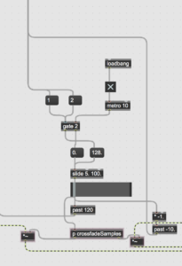
One challenge we faced was the accuracy of the ultrasonic sensor, which was influenced by the materials of clothing, such as cotton. Consequently, audience members wearing cotton were unable to trigger the sensor effectively. To address this issue during the exhibition, we provided an iron board as a prop for the audience to hold in front of their chests, enabling them to trigger the sensor. With more time and resources, an alternative solution could involve creating wheel-shaped props using laser cutting, incorporating the concept of “driving through time and space.” Adding a scenario or narrative to the project would help justify the use of such props.

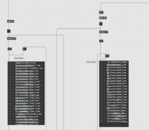
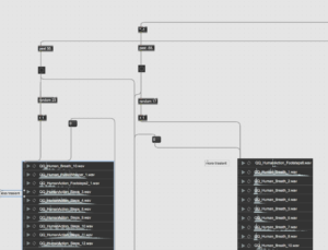
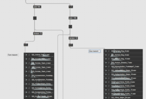
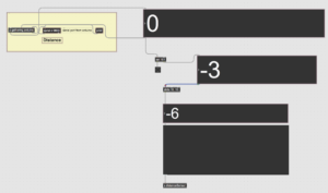
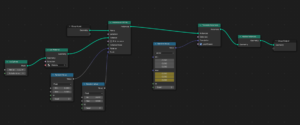
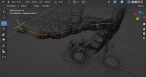
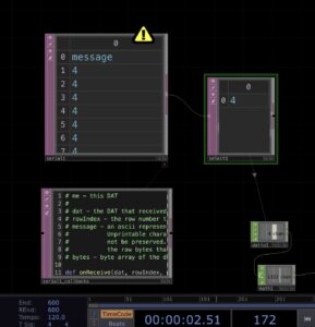
Another area of concern was the Kinect. As mentioned in a previous blog post, we disabled the Kinect function during the exhibition, as it interfered with the ultrasonic sensor, our primary interaction method. It would be beneficial to reintegrate the Kinect, given the time and effort spent on developing its engaging interaction features. One potential solution could involve changing the Kinect’s properties, such as using the y-axis data from movement capture instead of the distance between the user’s hands (x-axis data). This approach could offer similar visual effects without disturbing the ultrasonic sensor’s data collection while also providing more possibilities for visual elements and greater freedom for audience interaction.

Working within a large group, I learned the importance of time management and task organization, skills that are deceptively difficult to implement. I am grateful for the efforts of Molly and Dani, who effectively set up the exhibition, including designing the equipment displays, posters, postcards, guidebooks, 3D printing, and slideshows, providing a solid foundation for a successful exhibition. David’s exceptional leadership allowed each team member to find their tasks, make decisions, and ensure we were on the right track. Xiaoqing, Chenyu, and YG were consistently receptive to suggestions and supportive of others. Finally, I appreciate the assistance of Yijun and Yuxuan, with whom I collaborated on TouchDesigner, and who patiently addressed my questions.

Thanks for all the teammates!


Allison Mu

Exhibition Day – Zhu Yuanguang

On the day of the exhibition, setting up the audio equipments on live was relatively complicated, first of all, we needed to get a bunch of audio equipments we had booked in the Music Store. How to arrange the audio cables and power cables more efficiently and how to arrange the audio cables and power cables without hindering the audience’s visit and feeling became the main focus of my attention. In order to prevent the speakers from falling off accidentally, we also reinforced each speaker with tape. The cables were not allowed to pass through the audience experience area in order to reduce the risk to the safety of the audience and the safety of the installations.

After experiencing the visual and auditory impact of our group’s project in person during the testing phase of the project on the day of the exhibition, I was very excited because I was confident in our project from the testing phase.

After the exhibition had started, I continued to observe the expressions and reactions of the audience to our project, and I also talked to some of them to get their feedback on our project. I have to say that many of the audiences were very interested in our project and gave us good feedback on our project.

Although the whole exhibition would be a lot of work for every member of the group, I think it was all worth it. If there is another opportunity to do another exhibition like this, there are better solutions I think in terms of live audio installation settings to support the immersion and surround sounds of the project.

In the future, I think this project could be used to show details of historical buildings, future architectural visions and real-life immersions and studies, which could be more visually intuitive and aurally enjoyable for the audience. In this project exhibition, as I personally did not have the relevant courses for the other members of the group, it was refreshing to learn what they learned in the course, and to learn a lot about what Max could do in practice and what we could do with the software and sensors, which really made me curious about Max. I hope to learn how to use Max afterwards to create something like this project, which has not only cultural but also commercial value, which is great.

Exhibition Day – Allison

What I did

1.  Completed the remaining animations.

2. Set up TouchDesigner on the school’s PC.

3. Installed Kinect and configured the ultrasonic sensor.

4. Conducted final testing of interactions by connecting both MAX and TouchDesigner (previously tested separately).

5. Interviewed audience members for feedback.

6. Filming

Collecting feedback from the audience and our professors proved valuable, as it offered an alternative perspective on our project. As designers, we may overlook certain aspects during development, and third-party viewpoints can provide more objective opinions, contributing to future iterations.

Challenges Encountered

Despite our best efforts, we faced several last-minute challenges with this project, including unexpected technical issues. Although we shifted to a PC for increased power to run TouchDesigner, the performance did not meet our expectations, with glitches appearing frequently. Additionally, using Kinect interfered with the ultrasonic sensor triggering and disrupted the audio. When users manipulated the point cloud with gestures, the ultrasonic sensor below the Kinect was affected, sending incorrect data to MAX. Ultimately, we decided to disable all Kinect effects to prioritize overall performance.

Lessons Learned and Team Collaboration

The key takeaway from this experience is the importance of thoroughly testing equipment before implementing it in the final project and having a backup plan for unforeseen situations. Our team members’ collaborative efforts, active communication, and problem-solving skills were instrumental in overcoming challenges and achieving project success. By maintaining open lines of communication, we were able to address and resolve the aforementioned difficulties more effectively.


Allison Mu


TouchDesigner Point Cloud Camera Animation#2

With the assistance of Yijun and Yuxuan, I have learned how to make camera animations in TouchDesigner more efficient. As Yuxuan may have mentioned in his post, TouchDesigner Point Cloud Camera Animation #1, operating the camera in TouchDesigner entails a significant workload. Six parameters need to be adjusted for each frame, and alterations to one property can impact the others, resulting in a more time-consuming process than anticipated.

A New Approach to Visual Representation

We have decided to slightly modify the visual representation of the New Steps project from our original plan. Rather than creating one animation moving up to the top while another presents one step down, we aim to develop two animations from distinct perspectives: first-person and third-person views. This fresh approach offers various possibilities for point cloud scanning, allowing the audience to experience the visuals from multiple angles.

Developing the Animation

The animation I created showcases an overall view of the New Steps, with the camera slowly moving up and then descending to focus on people. This perspective provides a sense of daily life and what the scene might look like in reality. The combination of familiar and surreal visual experiences could potentially evoke reflection on the concepts of place and non-place.

A Multifaceted Visual Experience

By implementing different camera perspectives and enhancing the efficiency of our TouchDesigner animations, we aim to create a more immersive and multifaceted visual experience for our audience. The unique combination of familiar and surreal elements will encourage viewers to reflect on their understanding of place and non-place in a fresh and engaging way.

If you’re reading this in order, please proceed to the next post: ‘Kinect Phase 1’.

Allison Mu


Integrated Sound Triggering System #1 The function and structure of MAX

Overview

The interactive sound component of the device is designed to receive data from the sensors and to map the sensed data generated by the tester in real time to the intended sound sample in Max. Therefore, in this part of the concept, the state of simulated human climbing a step is transformed into a trigger and a random event for the tester for a certain threshold range.

Max 

The Link of Max Patch(with sound libraries):

https://drive.google.com/file/d/1ylP1ThA-mZn0tlwyI7ectMkIi0DuK2zL/view?usp=sharing

Threshold control:

Firstly, the Max patch needs to receive distance sensor values from the Arduino. These values represent the proximity, or distance, of a person to the stairs and it changes as the person goes up or down the stairs. Max patch receives distance sensor values from the Arduino, representing the proximity or distance from the person to the stairs. It compares the received distance sensor values with the threshold values 55 and 155 to determine the different states of climbing the stairs.

When a certain threshold range is reached, the sensed data is automatically detected and a different result is triggered. For example, with 55 and 155 as the two thresholds for ResultA/B, ResultA’s Playlist is triggered when the data is less than 55, ResultB’s Playlist is triggered when the data is greater than 155, and the Playlist for intermediate state sound files is triggered when the data is between 55 and 155.

In the final Max patch, the device is triggered by two thresholds that determine the distance value in real time. the “Past” object in the Max patch simulates the state of a person climbing a staircase using the distance sensor value received via the Arduino, and the “Past” object has four states during the determination process. The thresholds 55 and 155 are used to detect when the person has climbed the stairs and returned to the middle state from the previous step, respectively. A negative threshold of opposite polarity multiplied by -1 is used to indicate the return state.

When the first threshold is triggered (going up a step), the distance sensor value crosses the threshold 55 from low to high, triggering the first threshold in the patch indicating that the person is going up the stairs. This may result in a positive value being stored in the “past” object indicating the current state of the stairs. When the second threshold is triggered (returning to the intermediate state from Step up), the distance sensor value crosses the threshold 55 from a high value to a low value, triggering a second threshold indicating that the person is returning to the intermediate state from Step up. This results in a negative value being stored in the “past” object, indicating the current state from Step back to the intermediate state. When the third threshold (going down the stairs) is triggered, the distance sensor value crosses the threshold 155 from a low value to a high value, triggering the third threshold, indicating that the person is going down the stairs, storing a positive value in the “past” object, indicating the current state of going down the stairs. When the fourth threshold is triggered (returning to the middle state from the bottom of the stairs), the distance sensor value crosses the threshold 55 from the high value to the low value, triggering the fourth threshold, indicating that the person is returning to the middle state which is the middle state at the bottom of the steps, resulting in a negative value being stored in the Past object.

It is worth noting that the negative value triggered in the above step is multiplied by -1 using the multiplication object in the Max patch. this changes the sign of the value in a mathematical sense and in this case effectively indicates the opposite direction of the return to the intermediate state from the top or bottom of the step, enabling the simulation of the change of state of the person going up and down the stairs in the Max patch.

sound containers ( Random ) :

Vertically, a Playlist is created that randomly plays different fetch sound objects, i.e. containers of sound objects corresponding to the two extreme sound states of ResultA/B. Horizontally, it is necessary to create the corresponding sound containers for a range based on the actual measurement of different value intervals containing multiple transformations of the same sound file from ResultA to ResultB.

Within the framework of the above thresholds, I set up four sound playlist objects so that each time a threshold is triggered, the destination sound sample playlist can be played at random. According to the original design of the interaction-triggered sounds, the target sound playlist was broadly divided in the auditory category into realistically inclined sounds in the range of action-return states with a threshold of 55 and non-realistically inclined sounds in the range of action-return states with a threshold of 155. However, based on the results of the subsequent tests, the four sound playlists were further divided into Transient and Sustain in terms of their nature. The aim was to simulate a more realistic human speed state when walking up and down stairs.

Transients and continuations of sound:
When the observer is going up the stairs, all sounds within the random sound playlist are sustained, whereas when the person is returning to the intermediate state from a step, their simulated counterpart is the opposing state of going up the steps, so the target sample sound playlist is more transient, so the sound response triggered when returning to the intermediate state value is more rapid and more curved. The same purpose applies to the triggering of Threshold 155, but we wanted the sound triggered when descending the stairs to be more transient and Transient, and the sound response when returning from the step down to the intermediate state value to be more continuous and granular.
Transitions and connections of sound:
Since the observer is in constant motion during the action, this places certain demands on the transition between the different sound sample playlists. In the max patch we use the “gate” and “slide” objects to smooth this out. The go and return states of the threshold are sent to the left entry of gate via messages 1 and 2. The gate object receives the threshold and determines whether the input value is above or below the threshold. The output of the gate object is then sent to the slide object which controls the duration of the transition. The output of the slide object is then connected to the input of the scale object, which maps the duration value to the appropriate range for the playlist transition. The duration of the slide depends on the findings of our team’s listening experience in subsequent tests, and is the amount of time it takes to cross-fade between tracks. Loadbang and metro objects are used to trigger the transition at the appropriate time. This part of the Max patch can therefore be used to ensure that the sound playlist transitions smoothly and seamlessly according to the changing sensor input values.
Intuitive and Flexible Sound Transition Control:
In Max patches, the number 101 is used as a default or fallback value when sensor data is out of its range or not received correctly. This is a design choice used in the Max patch to handle unexpected or invalid inputs. For example, if the sensor is not sensitive enough or does not detect any input, it send an incorrect or invalid value to the Max patch. In this case, the Max patch is designed to replace the value with the default value of 101 to avoid unexpected behavior in the rest of the patch. Due to this phenomenon, our Max patch uses a “sel 101” object connected to a button object and has two outlets. The number “101” is used as an argument to the “sel” object, which means that when it receives the number 101 as input, it will output a “bang” message from the first outlet and the second exit will output whatever input is received. When the button object is pressed, it sends a “bang” message to the “sel 101” object. If the input number is 101, the first exit of the “sel 101” object will output a “bang” message, triggering some action in the Max patch. If the input number is not 101, the second exit of the “sel 101” object will output the input message unchanged. The number 101 is used as a trigger in Max patches to control a specific action or behavior. We connect its output “sel101” to a bang object that will trigger a specific function or event in the device when it receives the value 101. This is useful for handling unexpected input from distance sensors or implementing specific behaviors in your device based on this input.
Introduction and workflow of Arduino part:
Trigger sound design ideas and production process:https://blogs.ed.ac.uk/dmsp-place23/2023/03/23/interactive-trigger-sound/
Max and Arduino overall architecture testing process:
If you’re reading this in order, please proceed to the next post: ‘Integrated Sound Triggering System #2 The function and structure of Arduino’.

Sound Installation Setup in Exhibition

The surround sound installation in this exhibition provided a great immersive sound experience for many audiences. From talking to the audience, I found that there was a high level of interest in the sound installation and how it should be set up, so I would like to explain the idea of the sound installation and how it was set up in the exhibition.

For the sound installation in the exhibition, I initially set two plans, and I think the best sound installation plan would be the one I mentioned in my previous blog, Plan A. Firstly, the digital mixer DiGiCo SD11 and DiGiCo UB MADI Audio Interface would reduce unnecessary cables for the connection between our audio equipment and the audio channels. Secondly, the digital mixer would provide us with the greatest convenience in solving the gain level of the live sound without worrying about overloading live sounds and other unnecessary problems; finally, the digital mixer could provide some internal digital effects for live sound adjustment or live presentation to provide more options for the sounds of our project. Therefore, we learned about the SD11 in the early planning stages. Of course, the use of digital mixer in a live setting without the addition of a spare digital mixer confirms that there may be a certain risk to live presentation. Unfortunately, I was unable to use the digital mixer on the day of our presentation for a variety of reasons, which I felt slightly upset.

In sound installation setup Plan B, we replaced the digital mixer with an analogue console, the MIDAS Venice F, and changed the sound interface from a MADI sound card to an RME FireFace UCX. To some extent, this would reduce the efficiency of the live sound installation setup. However, this plan may be more reliable than Plan A, and may be slightly less rich in internal features than Plan A. This would mean that other members of the sound team may need to do more post-production work when designing the sound to ensure that the live sound could be perfect for the audience. Ultimately, Plan B could not be realised for a variety of reasons.

Our final solution in the live setting is to have the computer demonstrating the sound directly connected to a sound interface with ten output signals for live sound reinforcement. In the live test phase, we mainly did the following settings in terms of speakers connected to the sound interface, the front left speaker connected to the first channel of the sound interface output, the front right speaker connected to the second channel of the sound interface output, the front centre speaker connected to the third channel of the sound interface output, the left speaker connected to the fourth channel of the sound interface output, the right speaker connected to the fifth channel of the sound interface output, the rear left speaker connected to the sound interface output sixth channel, the rear right channel speakers connected to the sound interface output seventh channel, the front subwoofer connected to the sound interface output eighth channel. The live sound control was primarily controlled by the computer demonstrating the sound. During the live test phase, we also set a standard setting on the level of all the speakers and tested all the channels to see if the sound went smoothly. This plan would require relatively more audio cables as far as Plan A was concerned.

For this exhibition, all the audio equipments we needed for the live presentation was booked a week in advance in the Music Store, but due to the large number of DMSP Groups that needed to exhibit at the same period, there were many problems in booking the equipment, such as not having enough 8030 speakers to replace the 1030A speakers or not having enough speaker stands etc. Fortunately, all the problems were eventually solved.

I worked more on setting up and assembling the sound installation, so at other times I recorded the work of the other team members, taking photos and videos, and produced two clips as a trailer and a summary of the project, which I have shared with the group for their use and reference.

DMSP Place Group Trailer

DMSP Place Group Exhibition


If you’re reading this in order, please proceed to the next post: ‘Usability in the Exhibition’.

Kinect Phase 1

In our recent exploration of TouchDesigner, we identified Kinect as a promising tool to offer audiences increased freedom and opportunities for interaction with on-screen visual elements.

Kinect’s Versatility in Various Domains

As noted by Jamaluddin (2021), Kinect was initially designed for gaming purposes, but its application has expanded into other fields. The release of Microsoft’s SDK has enabled its use in medical, robotics, and other sectors through academic research projects, showcasing its adaptability and potential for innovation.

Integrating Kinect with TouchDesigner

By incorporating Kinect into our TouchDesigner workflow, our design team can utilize the motion data captured by Kinect to generate interactive and responsive visuals. Kinect’s real-time data can be seamlessly processed and manipulated in TouchDesigner, enabling the creation of more captivating point cloud effects based on audience movement.

Acquiring Kinect and Initial Testing

To our surprise, we were able to acquire a Kinect device from Ucreate in the library, prompting us to begin developing with this tool alongside Arduino. I followed an online tutorial by The Interactive & Immersive HQ (2020) to complete the initial Kinect connection test (see Figure 1). This straightforward tutorial provided essential information about both Kinect and TouchDesigner. Key takeaways included installing the Kinect SDK first, using CHOP objects to import data from Kinect into TouchDesigner, and understanding the various applications of this data, such as triggering color changes, deformation, and more.

Figure 1: Interacting with particles in TouchDesigner using Kinect, with the Kinect device placed on a ketchup bottle.


Next Steps and Collaboration

Moving forward, the Kinect device will be handed over to Yijun Zhou for further development of gesture-reactive effects. Please refer to the subsequent post for more information on our progress.

If you’re reading this in order, please proceed to the next post: ‘Kinect Phase 2’.

Allison Mu


Reference

Jamaluddin, A. (2021) 10 creative and Innovative Uses of Microsoft Kinect, Hongkiat. Available at: https://www.hongkiat.com/blog/innovative-uses-kinect/

The Interactive & Immersive HQ (2020). Generative visuals with particles & kinect in touchdesigner with Crystal Jow. YouTube. Available at: https://www.youtube.com/watch?v=mY7DavB0z2c


Blender Animations and Renders

As discussed in the initial brief for this project, the interactive space is comprised of three projected screens. The one directly in front of the user is occupied by the Touch Designer interactive imagery. The screens on either side of the user were originally planned to be connected to the Touch Designer project and have all three images be synced, however, as the weeks progressed, it was found that this feature would need more time to develop.

Therefore it was decided to revert to our backup plan of manually animating a camera moving up and down the virtual 3D model of the stairs and simply rendering and exporting this as a looping animation.

As discovered previously, using unity to handle the size of these point clouds was simple not feasible, even when running on university provided desktop computers. So instead, we used with Blender. Having never used the animation feature in Blender before, I viewed this as an opportunity to learn a new skill and experiment with the software’s capabilities.

Before starting the camera movement, I knew that I wanted the points in the point cloud itself to be animated in some way. After some research, I discovered this YouTube tutorial that was extremely helpful in explaining how to simply animate a collections of points that have geometry (Bazueva, 2022).

Following this I created a text render with a static camera and a single light:

In the geometry node editor, it is the random value that effects the x,y,z translation of the points that is animated. This adds an additional layer of movement that is separate to the camera. Moreover, it conveys more of the sense of non-place.

In the final renders, two cameras were added into the scene, one facing “left” and the other “right”, as if you were stood on the stairs and looked side to side.

They were then animated to follow along a Bezier curve that was manually drawn.

Lights were added onto the staircase to illuminate the points. The colours of the lights reflected the time of day that the scans were taken.

The bottom of the stairs = 6am, dark outside = dark blue colour light.

Mid stair = 1pm = light, yellow, almost white light

Top stair = 6pm = twilight/dusk, a dark purple, blue colour.

For the sake of time, I only rendered each camera in one direction. Then they were taken into iMovie by Daniela and made into a bouncing loop so that the motion went up the steps, then back down, back up etc.

In order to sync up the videos in the exhibition, the most simple method was to count down from three, and to press play at the same time on the respective computers.

The Final Result

Left video:

Right video:


There were some really interesting effects created by the movement of the points. It turned out as more of an abstract video due to the focal distance of the camera and the lower population of points compared to some of the heavier point clouds. I would have liked to spend more time compiling these videos on a computer with higher processing power. However, as they are I believe it still created an interesting effect for the experience.

If you’re reading this in order, please proceed to the next post: ‘The New Steps 3D Model’.

Molly Munro

References

Bazueva, M. (2022) Blender 3.1 Tutorial | Particles with Geometry Nodes, www.youtube.com. Available at: https://www.youtube.com/watch?v=XbBIRkmrZX0 (Accessed: 23 April 2023).


Arduino 3rd stage – Connecting to Touchdesigner!

After several practice sessions with Arduino, our team is ready to progress to the next stage of our project, as previously outlined in our blog posts. The goal is to detect the movement of audience members in order to trigger the playforward or playback of an interactive animation. Ideally, we would directly connect all the sensors with the software used for creating visual elements, such as TouchDesigner or Unity. Although we initially devised a backup plan to trigger recorded video through Processing, the results were not optimal, warranting further exploration of our primary option.

Experimenting with Arduino and Unity

During a weekly meeting, Molly and I attempted to connect an Arduino joystick with Unity. However, we discovered that compatibility was limited to specific versions of Unity that allowed for Arduino integration. As a result, we decided to shift our focus to TouchDesigner, which offered more online tutorial videos and implementation support.

Learning from Online Tutorials

I followed two instructional videos on YouTube: one demonstrating how to link Arduino with TouchDesigner by P.G. Lucio (2021), and another explaining how to control video playback with audio input by Bileam Tschepe (2022). These tutorials guided me through obtaining the correct data from the Arduino board, displaying messages with a serial port object in TouchDesigner, and processing the average data as input (see Figure 1). Additionally, I experimented with connecting distance data to video length to approximate the final project outcome (Figure 2).

Figure.1. Screenshot of serial port information in TouchDesigner.

Figure.2. The distance sensor is operating the video play.

Preliminary Results and Next Steps

Our initial tests have yielded promising results. We can now jump to different points in the video based on input from distance sensors, although the exact ratio between time (minutes) and distance (centimeters) requires further refinement. We have also successfully utilized audio beats to trigger video playback at this stage.

As our Arduino testing phase nears completion, I am eager to collaborate with Yijun and Yuxuan on the TouchDesigner aspect of the project. Acquiring TouchDesigner knowledge will be crucial in case we encounter issues with the software or if ultrasonic sensors prove unsuitable for influencing point cloud properties. Additionally, the integration of Kinect technology should also be considered in our ongoing development process.

If you’re reading this in order, please proceed to the next post: ‘From Raw Data to Unity’.

Allison Mu.


Reference
Bileam Tschepe. (2020, February 16). Controlling Video With Audio – TouchDesigner Tutorial 14 (see description) [Video file]. Retrieved from https://www.youtube.com/watch?v=oviwpILXo5A

P. G. Lucio. (2021, September 7). How To Use TOUCHDESIGNER & ARDUINO Together – Beginner Tutorial [Video file]. Retrieved from https://www.youtube.com/watch?v=V_Q_fDukTI0


Exhibition Day – Yuxuan

What I did

  1. Solved the scene switching triggered by the distance sensor in Max with David
  2. Set up TouchDesigner on the school’s PC.
  3. Installed equipment and configured Touchdesigner for presentation mode.
  4. Conducted final testing of interactions by connecting both MAX and TouchDesigner.
  5. Borrowed and set up the recording equipment.
  6. Filming

Challenges Encountered

On the exhibition day, I encountered a challenge when trying to link Max with TouchDesigner. As we didn’t conduct a complete test in advance, we set two fixed points in TouchDesigner for using the distance sensor, and the audience triggered the scene switching by walking between the two points. However, in Max, David set three fixed positions, and the audience’s position will switch between these three points. If we had followed the previous plan, the scene would have frozen in the transition when the audience stood in the middle position, and they would not be able to see a complete scene. Fortunately, after communicating with David, he modified the trigger value of the distance sensor in Max. As a result, the scene will switch when the user moves between the three adjacent positions.

The second problem we encountered was related to the equipment. Due to the highly complex interaction logic and large point cloud file imported into the TouchDesigner project, as well as the fact that the Kinect only supports Windows systems, it was difficult to run the project successfully on our laptops. Although we borrowed a computer from the school for the demonstration, it encountered some malfunctions on the day of the presentation, which caused severe lag and even prevented us from re-linking to the point cloud file in TouchDesigner. In the end, we had to set the point cloud file in an external hard drive on our own computers and run the project on the school’s computer through the external hard drive. This cost us a lot of preparation time.

The third challenge we encountered was related to the version of TouchDesigner. As we were using a non-commercial version and there was no free student version available, the resolution of our presentation was limited to 1280*1280, and we could not cover the entire screen when presenting in full-screen mode. Fortunately, with the help of Molly and Dani, we were able to enlarge the projector screen, so the presentation window was not affected.

Lessons Learned and Team Collaboration

This project made me realize the importance of thorough testing before presenting a project to the public. Although we tested the equipment in advance, our features were not fully designed, and the visual and sound aspects were not tested simultaneously, leading to many unexpected situations on-site. Fortunately, we were able to solve most of the problems before the presentation. This was also my first time working in a team of nine people, and I realized that timely communication and collaboration are crucial in a large team. Updating progress and sharing problems in a timely manner can make team collaboration more efficient.


Yuxuan Guo

css.php

Report this page

To report inappropriate content on this page, please use the form below. Upon receiving your report, we will be in touch as per the Take Down Policy of the service.

Please note that personal data collected through this form is used and stored for the purposes of processing this report and communication with you.

If you are unable to report a concern about content via this form please contact the Service Owner.

Please enter an email address you wish to be contacted on. Please describe the unacceptable content in sufficient detail to allow us to locate it, and why you consider it to be unacceptable.
By submitting this report, you accept that it is accurate and that fraudulent or nuisance complaints may result in action by the University.

  Cancel