Any views expressed within media held on this service are those of the contributors, should not be taken as approved or endorsed by the University, and do not necessarily reflect the views of the University in respect of any particular issue.
We have put together a max patch that semi-generatively produces a soundscape for the installation, it chooses tones from a list by random, and also changes the pitch between two set variables randomly each time, to give more of a naturalistic output.
It also has space for more than one set of tones, and more than one atmospheric tone, once implemented these will be used for the changing nature of the installation.
1. OSC Broadcast Implementation:
– Utilize OSC (Open Sound Control) broadcasting to transmit signals from the main node to all connected nodes simultaneously, eliminating the need for individual transmissions.
– Add “255” to the end of the IP address to enable broadcasting across the entire network, serving as the broadcast frequency.
2. NEED: USB-C Cable Requirement:
– Ensure each M5 device is equipped with a USB-C connection; therefore, we need to get 7 USB-C cables to facilitate connectivity.
3. Communication Testing with M5 Sticks:
– Conducted coding exercises to ascertain the capability of M5 sticks connected to the same network to exchange messages. Demonstrated successful data transmission between M5 sticks, validating the feasibility of custom code deployment for activating sounds or LEDs.
4. Light Testing Phase:
– Plan to conduct isolated testing of LED neopixels on M5 sticks.
– Incorporate the ‘adafruit.neopixel’ library into the codebase to enable control functions for the LEDs.
– For the code: Specify the ring’s LED count (12 LEDs) and develop an object to manage LED activation with customizable colours.
– Emphasize adjusting brightness levels (0 to 255) instead of simple on/off toggling to accommodate potential signal delays.
5. Integration of Additional Sensor:
– Investigate compatibility of an additional sensor with the M5 devices and network infrastructure, including potential connectivity to laptops.
6. Network Setup:
– Establish a designated M5 stick network named “m5node” with password “12345678” to facilitate seamless communication.
– Confirm successful message transmission and reception among M5 sticks.
– Observe functionality of light pulsing and color-changing sequences.
Next Steps to have before next meeting:
– Proceed with soldering the neopixels.
– Fine-tune data of M5 sticks on Max patch, then add that data to the code.
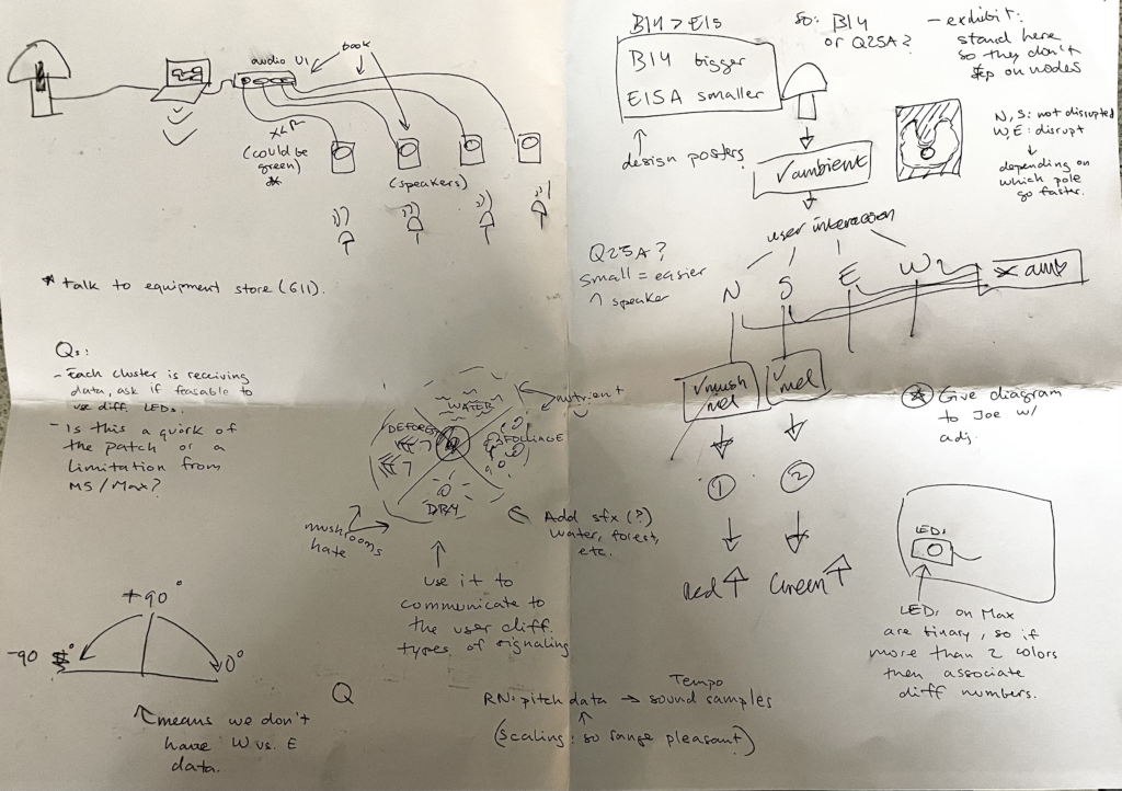
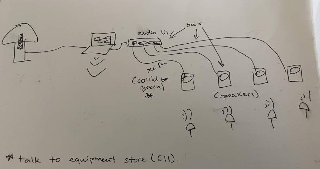
This diagram illustrates the main mushroom on the left connected to a laptop, which in turn is linked to an audio interface. Instead of relying solely on a single speaker or utilizing speakers provided by the location, the decision was made to enhance the immersive experience of the installation by employing smaller speakers, one for each node. Ideally, these speakers will be connected to the user interface using green XLR cables. This approach aims to improve users’ understanding of the correlation between light flickers and sound, as both will emanate from the same direction.
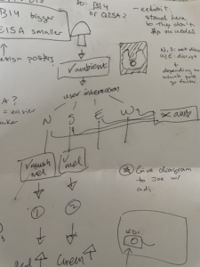
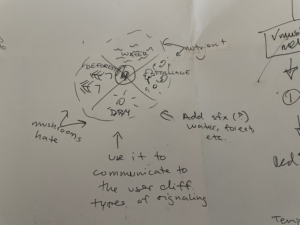
Showing 4 different poles of interaction.Creating a diagram in which the node can be moved to.
In these diagrams, the concept of establishing four distinct “extremes of interaction” was investigated. The proposal suggests that along the North to South axis (up and down), the mushroom would maintain a balanced state of interaction, whereas along the West to East axis (left to right), it would exhibit a disrupted state. This disruption could be manifested through an increase in tempo in the corresponding sound. To facilitate user comprehension of this interaction and to deepen their understanding of the installation’s themes, the idea of creating a diagram depicting four factors that fungi favour or disfavour is explored, as depicted in the right image. For instance, if a node were oriented towards the west, resembling a sunny arid landscape, it would trigger the disrupted state, while orienting it towards water would induce the opposite effect.
During our exploration of potential locations, we visited rooms B14 and E15A. Following the tour, we concluded that B14 appealed to us more due to its aesthetic, characterized by broken walls and paint that align with our desired aesthetic. However, we had reservations about the space’s isolation in the ECA building and its popularity for other student projects. Conversely, this meeting took place in the Design and Digital Media room Q25, which features a storage area at the back, making it the most suitable option for our project for several reasons. Firstly, its accessibility facilitates regular work sessions leading up to the exhibit. Consequently, we settled on Q25.A as our chosen location.
Considering the compact size of Q25.A, we deliberated on the user experience of entering the space and conceived the idea of a U-shaped installation. This layout would allow users to enter the space without needing to navigate around it, enhancing accessibility and engagement.
Furthermore, we discussed the possibility of creating mushroom clusters instead of individual nodes. However, this decision remains unresolved, as the number of nodes will depend on the quantity of M5 sticks provided by Joe Hathaway.
For nearly two weeks, Shirin and I tried to find different ways to style the mushrooms in our project.
We tried making it by hand, using crepe paper and wire. We also asked ECA’s wood workshop about the possibility of using cut wooden boards to create the main structure. And asked the metal workshop about the difficulty of welding the theme structure with wire.
We also considered 3D printing, but this method does take a long time. However, there is no need for continuous manual operation during this period, so I think it is feasible.
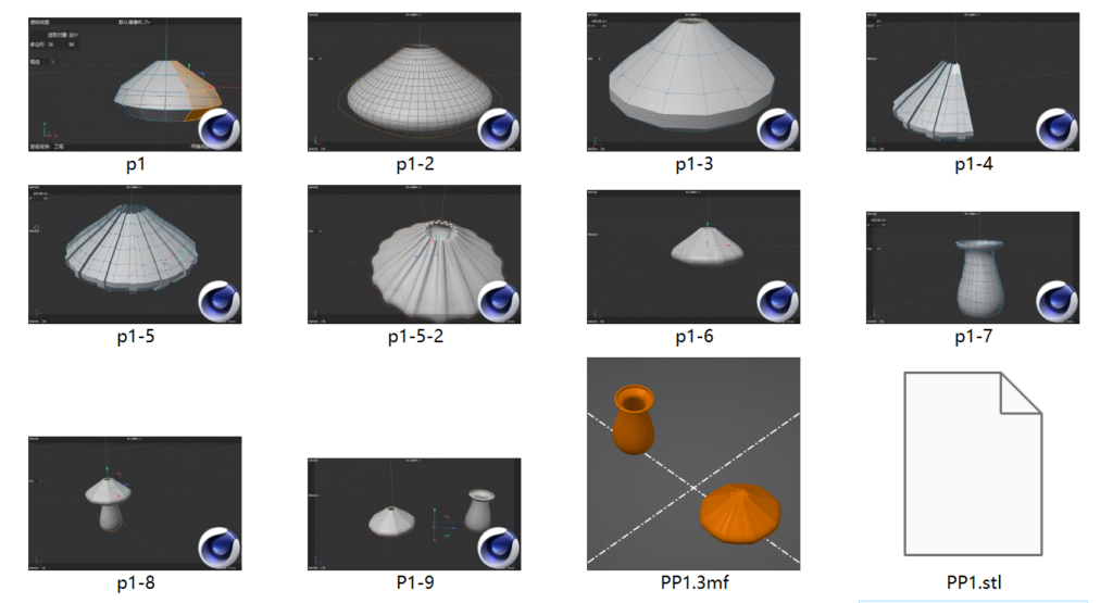
I’m trying to build a mushroom model in C4D. There are three key issues:
1. The size of the model. The maximum printable size of the 3D printer in the main library is 18cm*18cm*18cm. So I considered dividing the model into upper and lower parts, printing them separately and then splicing them together to expand the size of the mushroom.
2. Transparency of the model. The filament for the 3D printer in the main library is coloured PLA. Considering that in our project design, each mushroom will have different colours of luminous changes, in order to avoid interference, white PLA can be used. But this material itself is not very transparent. So I left a hole in the top of the model to let the light shine through.
3. The thickness of the model. At first, I wanted it to be as thin as possible so that some light could shine through. Later I realized that this would require higher printing accuracy, and was not conducive to later polishing. It may be more time-consuming. Finally, I increased the thickness.
I retained the internal hollow structure to facilitate the placement of sensors, lamp beads and wires in the physical model later.
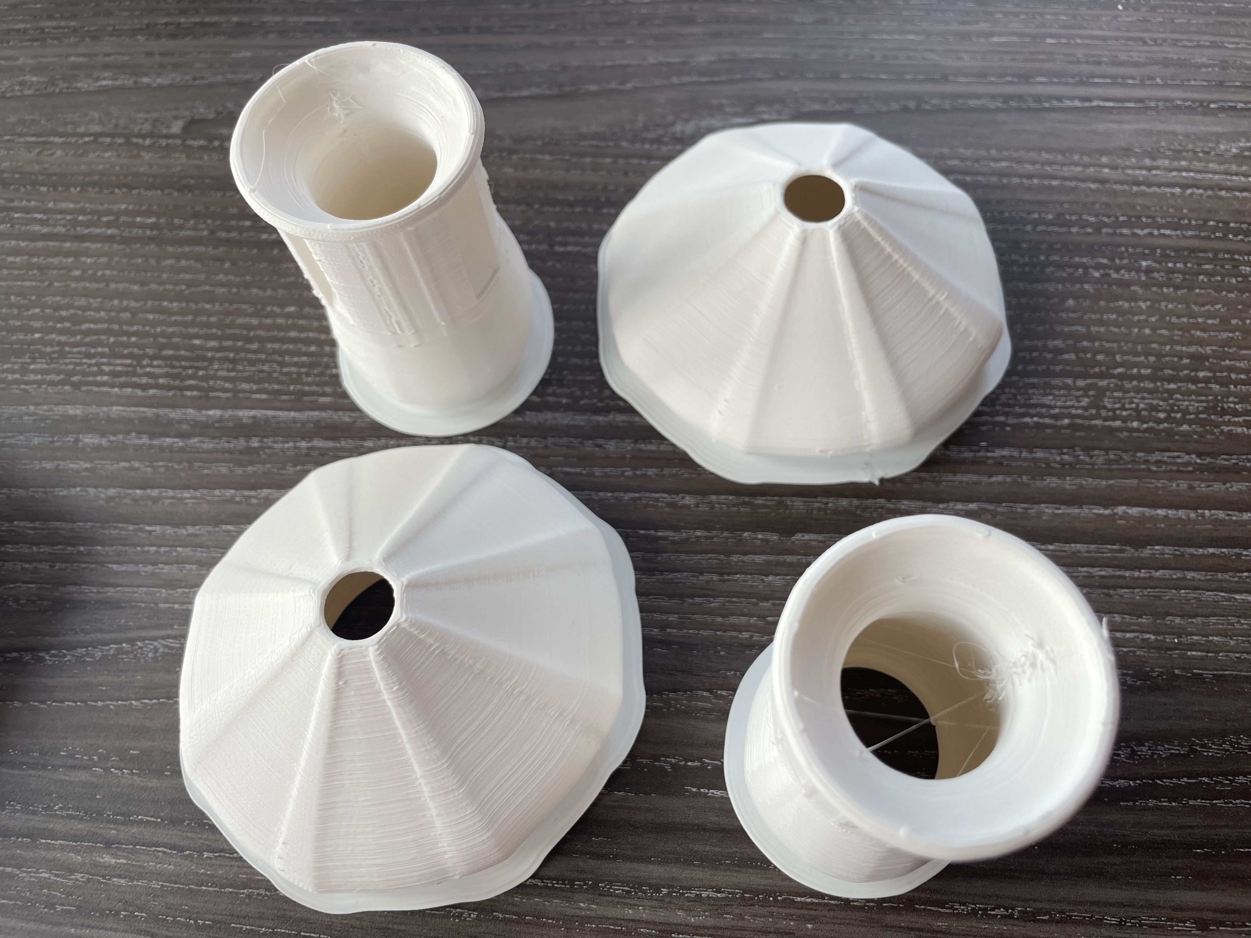
The Mushroom prototypes were designed by Agnes and 3D printed by Shirin at uCreate. After several attempts, the model was successfully printed using the fastest printer available. These two mushroom prototypes filled a single printing plate, resulting in a printing cycle of approximately 7 hours for both mushrooms using their fastest printer.
3D printed Mushroom nodes.
These are less than 18 cm in height.
Pros:
Easy to print once the model and printer are calibrated.
Estimated completion time for all prints is around 3 days (plus 1 additional day for post-processing).
Cons:
The material does not showcase light as effectively as crepe paper.
The finished product is small, raising concerns about its ability to adequately fill the space. This prompts questions about the need for additional exhibition elements and whether the entire space should be utilized.
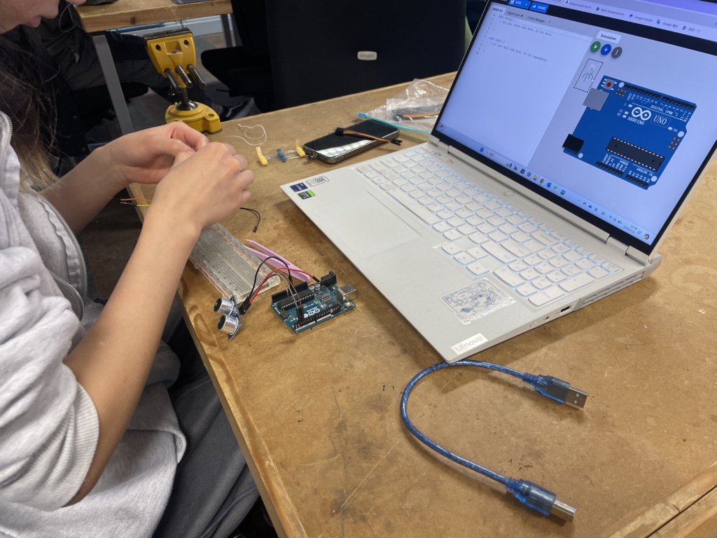
The purpose of this meeting was twofold: Firstly, to explore the feasibility of 3D printing the mushroom nodes. Agnes created a 3D file for this purpose, which was subsequently uploaded to the uCreate space machines. Secondly, the meeting aimed to initiate hands-on work with the electrical components.
For this purpose, Agnes set up a circuit, while I reached out to John Hathaway to schedule a meeting for next week to seek further assistance. We anticipate needing help with soldering as well. Additionally, we expect all the LEDs to arrive next week, so by around Wednesday, we could commence assembling everything.
These past few weeks, Agnes and I have been working at the uCreate space to brainstorm and test various concepts for designing the mushroom nodes.
Here are the three prototypes that we have been experimenting with:
Prototype 1: Umbrella
The first prototype was based on an umbrella-like structure. Due to our use of weaker paper, we were unable to shape it effectively with the wires inside, resulting in a design more reminiscent of a leaf than a mushroom. Additionally, we were dissatisfied with the appearance of the stem.
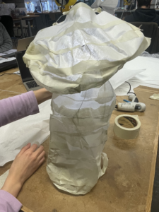
Prototype 2: Paper Lantern
After observing how light interacted with the previous paper model, we conceived the idea of constructing an aluminium wire framework covered in ideal paper and glue. Since we lacked the materials for this, we initially prototyped with masking tape. This process led us to the realization that creating eleven additional nodes using this method would be too time-consuming.
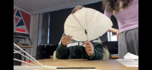
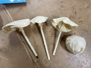
Prototype 3: Crepe paper mushrooms
This prototype built upon the first iteration, utilizing crepe paper to achieve more mushroom-like heads. Additionally, we repurposed 3D-printed scraps available at uCreate to create the stems. The texture of crepe paper enabled light to pass through, and its pliability allowed us to mould it into various shapes, as illustrated in the image above.
We are quite set on prototype 3, especially since there are only 3 weeks left but we have still contacted wood and laser cutting technicians at ECA workshops to see if a different approach is feasible with the time we have.